Horner APG SmartStack I/O HE-ADC920* User Manual
Page 3
MAN0317-09
10 NOV 2006
PAGE 3
ADC920
Information is subject to change without notice. SmartStack is a trademark of Horner APG, LLC.
4 CONFIGURATION
Note:
The status of the I/O can be monitored in Cscape Software.
4.1 Software
Configuration
Preliminary configuration procedures that apply to SmartStack
™ Modules are contained in the hardware
manual of the controller you are using. Refer to the Additional References section in this data sheet for
a listing of hardware manuals.
I/O Map Tab
The I/O Map describes which I/O registers are assigned to a specific SmartStack
™ Module and where the
module is located in the point map. The I/O Map is determined by the model number and location within
the SmartStack
™. The I/O Map is not edited by the user.
Module Setup Tab
a) Input range for each channel may be selected independently.
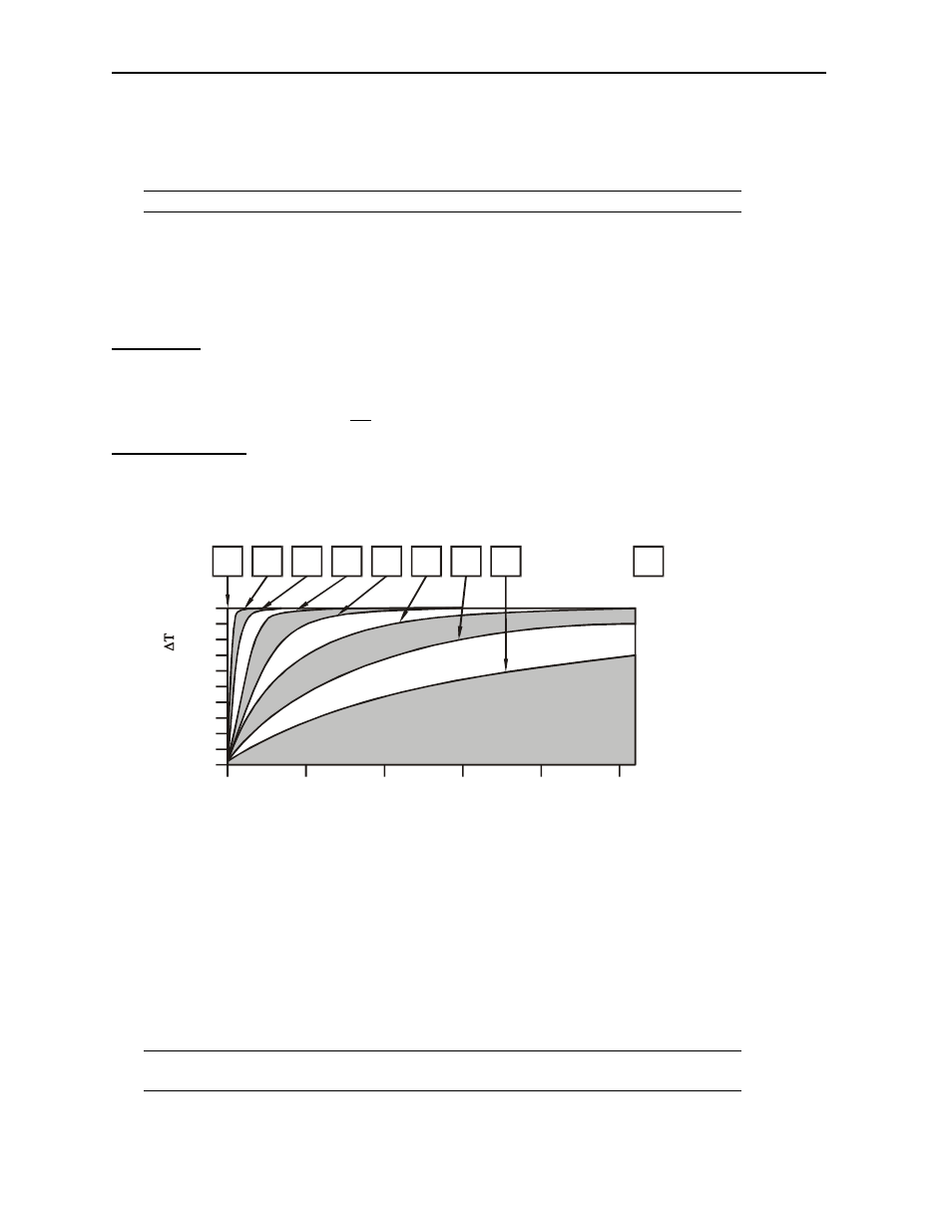
b) Filter Constant sets the level of digital filtering according to the following chart.
c) In addition to configuring the module setup, the hardware must be jumpered to select the
appropriate range for each channel.
Digital Filtering:
The illustration above demonstrates the effect of digital filtering (set with Filter Constant)
on module response to a temperature change.
4.2 Hardware
Configuration
The inputs are referenced to the bus common. Each of the inputs can be jumper-selected for one of the
three input types. Behind each of the input pins is a corresponding group of four jumper pins with a
programming plug.
a) To select 5V input: Connect the two pins nearest the connector.
b) To select thermistor input: Connect the two pins nearest input 1.
c) To select 20mA input: Connect the two pins nearest input 12.
Note:
It is also necessary to specify the input channel type in Cscape along with the
temperature format.
60
20
100
40
80
20
0
10
100
90
80
70
60
50
40
30
Scans
0
1
2
3
4
5
6
0
7
%
C
om
pl
et
e
[
]
Filter
Constant