Horner APG QX751 OCS User Manual
Page 2
MAN0889-03-EN
Specifications / Installation
__________________________________________________________________________________________________________________________________________________
11/20/2009 Page 2 of 6 1023
3
INSTALLATION
Note: Prior to mounting, observe requirements for the panel layout design and
adequate clearances in the QX Hardware Manual (MAN0890). A handy
checklist is provided in the Installation chapter.
3.1
Installation Procedures
a.
QX Base Installation
1. Per specifications of the QX751 model you are using, carefully prepare the panel
cutout. Make sure the corners of the cutout are square and free from burrs. (Locate the
panel cut-outs and dimensions as shown in this document.)
2. Cut the host panel.
3. Insert the QX751 (base unit only) through the panel cutout from the front. The gasket
material needs to lie between the host panel and the QX751.
4. Install and tighten the mounting clips (provided with the QX751) until the gasket material
forms a tight seal.
5. If used, install the Back Pack (BP) option. (Refer to Item b in this section for details.)
Note (Backpack sold separately in North America Only): QX units are shipped with
firmware that requires a Backpack for proper boot up to complete. If a Backpack is
not to be used, a QX firmware update from Cscape must be performed for proper
operation.
6. Connect cables as needed such as communications, programming, power and fiber
optic cables to the QX ports using the provided connectors.
7. As a final step before using, carefully remove the protective, plastic sheet from the front
of the unit. The protective, transparent sheet is used to protect the display window.
8. Begin configuration procedures for the QX.
b.
Back Pack (BP) Installation (Backpack sold separately in North America Only)
1.
Remove the clear plastic label on the unit.
2.
Push the BP into place on the QX Base.
3.
Insert and tighten the 4 screws.
3.2
Panel Cut-Out and Dimensions — QX751 (15-inch)
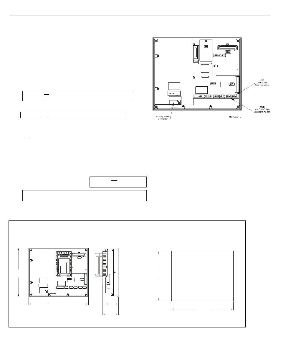
The QX base has power, network, programming, USB-A and USB-B ports. Three RS-232 and
RS-485 ports are available. (Refer MAN0890 for handy check list covering layout/clearances)
USB-A Port – USB flash drive
USB-B Port – Programming Port
001QX010
LAN
CN1 MJ1 MJ2 U-B U-A
CF
CN7
3.95”
[100.3mm]
15.07”
[382.7mm]
12.31”
[312.7mm]
3.19”
[81.1mm]
Figure 1 – Panel Cut-out and Dimensions (15-inch)
3.3
QX Base Ports and Connectors
Figure 2 – QX Base Ports and Connectors
Caution: Do not overtighten. Over-tightening damages the case.
Caution: Do not force the QX into the panel cutout. An incorrectly
sized panel cutout damages the QX screen.
QX751
15”
Caution: Do not over tighten. Over-
tightening damages the case.
14.54”
[369.4mm]
11.79”
[299.4mm]
Note: Spacer CAB00023 provided with Back Pack Rev G is not meant to be
used with QX751.