Ashcroft ATE-2 - Handheld Calibrator User Manual
Page 45
43
Both modules can display temperature units of Fahrenheit,
Celsius, Kelvin, Rankine, and also support reading output in units
of ohms.
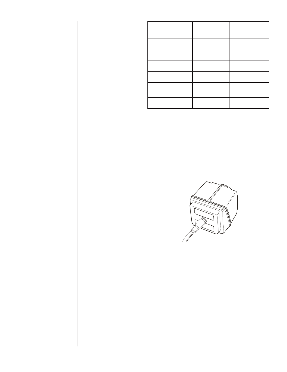
The electrical interface of the probe to the module incorporates
a Switchcraft TA4M type connector and requires an RTD with the
appropriate mating connector. The connector is available through
the supplier of your choice.
Setting up the PTE-2 for an RTD Temperature Measurement
Insert the appropriate XXX-RT Quick-Select RTD Interface
Module.
Connect the desired RTD probe to the Switchcraft connector on
the XXX-RT module.
Note: RTD probes can be connected using two, three or four wire
configurations. Use of four wire configuration is recommended for
optimum accuracy. RTD probes provided by this manufacturer are
of the four wire configuration.
To select RTD probe characteristics
Install an RTD Quick-Select Module and Probe in the HHC
Base Unit.
Press MENU key
Use DOWN or UP ARROW to highlight “Setup…”
Press ENTER
Use DOWN or UP ARROW to highlight “Module…”
Press ENTER
Use DOWN or UP ARROW to highlight “RTD…”
Press ENTER
RTD Module programming screen will appear
XXX-RT1
XXX-RT2
Ohms Measurement
Range
0 - 400 ohms
0 - 4000 ohms
Factory Programmed
RTD Probe 01
Pt100 385: -200 to
500C ±0.15C
Pt1000: 184 to 275C
±0.15C
Factory Programmed
RTD Probe 02
Pt100 392: 550 to
850C ±0.2C
----
Factory Programmed
RTD Probe 03
Ni 120: 80 to 260C
± 0.1C
----
Factory Programmed
RTD Probe 04
Cu 10: 70 to 150C
± 0.6C
----
Available User
Programmable R TD
Probes
4
7
Ohms
+0.01% reading
+0.02ohms
+0.01% reading
+0.2ohms
SECTION 15 j.
RTD TEMPERATURE
MEASUREMENT CONT.
Ꮨƽ