Erase counter apdu – MagTek IntelliStripe65 99875161 User Manual
Page 111
Appendix B. Memory Card Support
105
Command APDU:
CLA
INS
P1
P2
Lc
Data Field
00
D0
00
Adr
Len
Data to be written
CLA is always 00
INS is always D0
P1 is ignored
P2 is the address where the write will start
Lc is the number of bytes to write.
Data Field contains the bytes to write.
Response APDU:
SW1
SW2
Possible SW1/SW2 combinations:
SW1/SW2
Meaning
9000
Normal completion, no errors
Erase Counter APDU
The Erase Counter command is used to erase counter bytes of the card. For this type of card
erased means that each bit = 1.
If the specified address is not in the range specified by the Counter Lowest Address and the
Counter Highest Address properties, the command will not be processed.
This command writes bits of the addressed byte to 0 under control of the Erasure Mask. The
Erasure Mask is formulated to indicate one or more bits that can be written to zero and then
erasure initiated. If there are multiple zero bits in the Erasure Mask, multiple write to zero
followed by erasure operations will occur (all to the same byte).
The GAM375-BitOrder property dictates the order of bit processing.
If there is a need to erase multiple bytes of the Counter, multiple Erase Counter commands must
be sent in the proper order. Determining the order is the user’s responsibility.
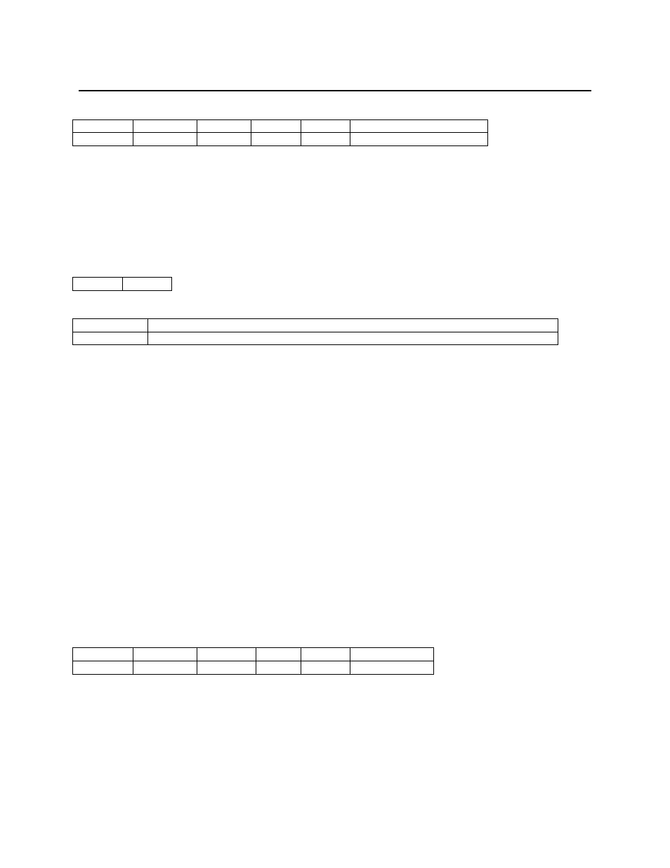
Command APDU:
CLA
INS
P1
P2
Lc
Data
D0
0A
xx
Adr
01
Erasure Mask
CLA is always D0
INS is always 0A
P1 is ignored
P2 is the address where the erase will occur
Lc must be 01
Data contains one byte giving the Erasure Mask.