DME Hydraulic Locking Core Pull Cylinders User Manual
Page 2
DME HYDRAULIC LOCKING CORE PULL CYLINDERS
Specification No. ME-E32-0001(C)
Part No. HLCP-PS01
Page 2 of 12
MOLD DESIGN CONSIDERATIONS (continued):
must “shut off” against an opposing core wall or face, so that plastic flashing is avoided. For proper “shut-off” as described above, recommended preload
amounts are provided in this document. Adjust the spacers prior to final mold assembly. Ensure sufficient pocket clearance around the piston rod and
spacer disk is present for smooth operation.
Positional alignment of the cylinder assembly is achieved by aligning the forward collet of the cylinder body (protrudes forward of the mounting flange)
into the mold plate via the outer diameter of the collet. The collet will protrude past the spacer disk. Rotational alignment of the overall assembly is
achieved via the mounting screws, as rotational alignment is only used to position the proximity sensors and hydraulic fitting connections and/or hoses
within the overall installation. The piston may freely rotate, therefore if rotational alignment of the sliding core is required, rotational alignment of the
sliding core must be achieved via other means.
The positional alignment of the mold’s sliding core is not to be maintained by the cylinder assembly’s piston. The sliding core must have it’s own
provision for positional alignment within the mold plate.
The suggested installation pocket details are based on the cylinder assembly being recessed into the side of the mold plate. It is possible to have the
cylinders assembly mounted fully “proud” of the side of the mold plate, however, positional alignment of the cylinder assembly to the mold plate requires
the forward collet (protruding forward of the mounting flange of the cylinder body) to be recessed partially into the side of the mold. Please adjust the
overall installation as required to fit your application, while maintaining minimum clearances for the hydraulic fitting connections and/or hoses, as well as
maintaining clearances for the proximity sensors. It is the responsibility of the mold designer and/or mold maker to select appropriate hydraulic fittings, as
well as provide necessary pocket clearances (where required) for the hydraulic fittings. Clearance for hydraulic service may need to accommodate hoses
or other features, in addition to the hydraulic fittings themselves. Standard hydraulic thread is NPTF type, but other types are available upon request.
Please see Detail 3.4 for additional notes regarding necessary clearance needed to accommodate the proximity sensors.
Mounting screws provided should not be modified (shortened). Ensure the tapped mounting holes are deep enough to ensure the screw heads can fully
seat on the mounting flange after the screws are installed fully and torque is applied.
SEE NEXT PAGES FOR SUGGESTED POCKET MACHINING DETAILS
TABLE 1.1 — LOAD CAPACITIES FOR THE DME HYDRAULIC LOCKING CORE PULL CYLINDER ASSEMBLY
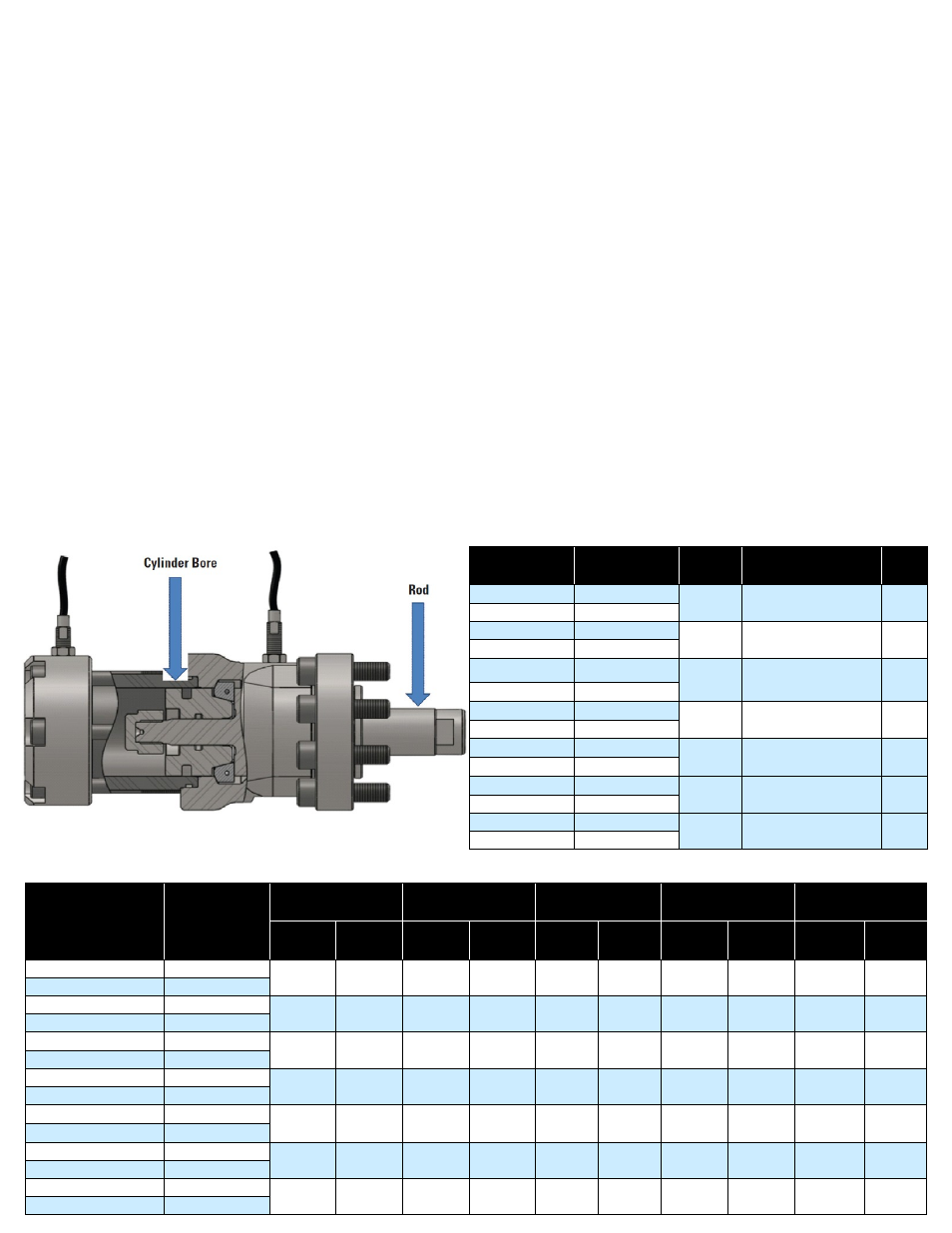
DETAIL 1.1 - HYDRAULIC LOCKIN CORE PULL ASSEMBLY
TABLE 1.0 — HLCP ASSEMBLY SIZES
ASSEMBLY No.
STROKE
ROD DIA. CYLINDER BORE DIA.
NPTF
TAP
HLCP060-1000
25.4 mm (1.00 in)
16 mm
(0.63 in)
30 mm (1.18 in)
1/8
HLCP060-2000
50.8 mm (2.00 in)
HLCP100-1250
31.8 mm (1.25 in)
20 mm
(0.79 in)
36 mm (1.42 in)
1/8
HLCP100-2500
63.5 mm (2.50 in)
HLCP150-1375 34.9 mm (1.375 in) 25 mm
(0.98 in)
45 mm (1.77 in)
1/4
HLCP150-2750
69.9 mm (2.75 in)
HLCP200-1750
44.5 mm (1.75 in)
32 mm
(1.26 in)
56 mm (2.20 in)
1/4
HLCP200-3500
88.9 mm (3.50 in)
HLCP300-2000
50.8 mm (2.00 in)
42 mm
(1.65 in)
71 mm (2.80 in)
3/8
HLCP300-4000 101.6 mm (4.00 in)
HLCP500-2500
63.5 mm (2.50 in)
50 mm
(1.97 in)
84 mm (3.31 in)
3/8
HLCP500-5000 127.0 mm (5.00 in)
HLCP750-3000
76.2 mm (3.00 in)
60 mm
(2.36 in)
105 mm (4.13 in)
1/2
HLCP750-6000 152.4 mm (6.00 in)
ASSEMBLY NUMBER
AT 160 BAR
(2321 PSI)
PRELOAD
Holding Force in kilo
Newton [kN]
Holding Force in
Pound Force [lbf]
Holding Force in
Metric ton [ton]
Holding Force in UK
(troy) ton [ton]
Holding Force in US
(avdp) ton [ton]
Without
Preload
With
Preload
Without
Preload
With
Preload
Without
Preload
With
Preload
Without
Preload
With
Preload
Without
Preload
With
Preload
HLCP060-1000
0.15 mm (0.006 in)
60
35
13,488
7,868
6.12
3.57
5.46
3.19
6.74
3.93
HLCP060-2000
0.20 mm (0.008 in)
HLCP100-1250
0.15 mm (0.006 in)
100
50
22,480
11,240
10.20
5.10
9.11
4.55
11.24
5.62
HLCP100-2500
0.20 mm (0.008 in)
HLCP150-1375
0.10 mm (0.004 in)
150
65
33,720
14,612
15.30
6.63
13.65
5.91
16.86
7.31
HLCP150-2750
0.15 mm (0.006 in)
HLCP200-1750
0.15 mm (0.006 in)
200
110
44,960
24,728
20.39
11.21
18.20
10.01
22.48
12.36
HLCP200-3500
0.20 mm (0.008 in)
HLCP300-2000
0.15 mm (0.006 in)
300
160
67,440
35,968
30.59
16.31
27.31
14.57
33.72
17.98
HLCP300-4000
0.20 mm (0.008 in)
HLCP500-2500
0.20 mm (0.008 in)
500
300
112,400
67,440
50.98
30.59
45.51
27.31
56.20
33.72
HLCP500-5000
0.30 mm (0.012 in)
HLCP750-3000
0.20 mm (0.008 in)
750
400
168,600
89,920
76.48
40.79
68.27
36.41
84.30
44.96
HLCP750-6000
0.30 mm (0.012 in)