DME 375 Series Front Load Heater User Manual
Danger warning
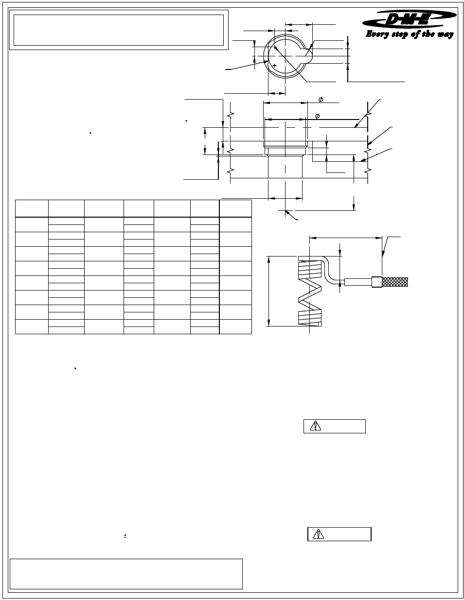
CIRCLE
INTERPOLATION
MANIFOLD
LINE
NOZZLE
PLATE
WIRE
SLOT
GATE
installing and/or removing heater
Please read carefully before
INSTALLATION DATA
375 SERIES FRONT LOAD HEATER
SCH9997 ME-X741-PS-253-E
"B
"
"L"
2.875
FLEXIBLE LEADS
AFTER THIS AREA
DISASSEMBLY PROCEDURE
1. Nozzle has been designed to have the tip removed in the press. See
recommendations and guidelines Note # 2 for keying nozzle to keep from rotating.
2. Careful attention should be taken to the heater / thermocouple leads as
damage could occur when working on nozzle assembly.
3. For removal of tip from nozzle, a six point deep well socket is recommended. The
nozzle must be at processing temperature and the heater should be turned off
when removing tip counter-clockwise from the nozzle.
4. For removal of heater recommendations and guidelines Note # 4.
DANGER
WARNING
Failure to comply will result in serious injury or death:
ELECTRICAL HAZARDS
Improper voltages or grounding can result in electrical shock. Use only
with proper voltage and a proper earth ground.
To avoid electrical shock, do not operate product when wet.
Do not operate this equipment with covers or panels removed.
To avoid electrical shock, turn off main power disconnect and lockout /
tag out before servicing this device. Do not connect temperature sensors to
electrical power. It will damage the product and it could cause fire,
severe injuries or even death.
If green ground wire present wire must be connected to the ground.
Do not rebend rigid leads. Rebending leads might result in damage to circuit.
Product might absorb moisture when cool. Use low Voltage or power to drive
out residual moisture before applying full power. Failure to do so may cause
damage to this product.
Failure to comply can result in serious injury or death:
STORED ENERGY AND HIGH TEMPERATURE HAZARDS
This product maintains molten plastic at high pressure. Use caution when
operating and servicing the system.
Physical contact with molten plastic may result in severe burns. Proper
protective equipment, including eye protection, must be worn.
This product has heated surfaces. Use caution when operating and servicing
the system to avoid severe burns. Proper protective equipment should be worn.
IMPORTANT SAFETY INFORMATION
A hot-runner system includes electrical elements and may contain molten
plastic at elevated temperature and pressure. To avoid injury, exercise
caution by reading these instructions before servicing or operating the
system.
These instructions must be passed on to the end user where they should
be read before using this product. Failure to do so can result in serious
injury or death.
D-M-E SHALL NOT BE LIABLE FOR MISUSE OR FAILURE TO FOLLOW THE ENCLOSED
INSTRUCTIONS AND SPECIFICATIONS. D-M-E HERBY TO DISCLAIMS ALL IMPLIED
WARRANTIES, INCLUDING MERCHANTABILITY AND FITNESS FOR A PARTICULAR
PURPOSE. IN NO EVENT SHALL D-M-E BE RESPONSIBLE FOR LOSS OF USE, REVENUE
OR PROFIT, OR FOR INCIDENTAL OR CONSEQUENTIAL DAMAGED.
"A" + BE
SEE NOTE
0.250 MIN.
0.750 MAX.
1.375
5 ft-lbs. For protection of the tip, a six
7.125
EHA2015
SCH2095
6.125
heat to transfer into the tip before molding.
6. Wait a minimum of 5 minutes after set point has been achieved for sufficient
EHA1015
manifold are removed to ensure seal-off.
5. Seal ring for nozzle body must be replaced each time nozzle body and / or
7.000
3. Firmly screw the tip into the shank of the nozzle body. Tighten and untighten two
or three times making sure there is a good contact between the tip and the nozzle.
SCH1095
1100
4. For removal of heater recommendations and guidelines Note # 4.
point deep well socket is recommended.
2. Apply an anti-seize compound on the tip threads.
Torque the tip into the nozzle using 30
1. Tip and nozzle threaded area must be clean of any material before reassembling.
ASSEMBLY PROCEDURE
09-08
EHA2014
SCH2094
1.375
0.875
CIB1373
"A"
SUB-ASS'Y
CAT.NO.
NOZZLE
BODY
CAT.NO
HEATER
CAT.NO.
WATTAGE
"B"
"L"
2.000
EHA1008
CIB1366
SCH1088
400
0.875
2.125
EHA2008
SCH2088
1.375
2.500
EHA1009
CIB1367
SCH1089
450
0.875
2.625
EHA2009
SCH2089
1.375
3.000
EHA1010
CIB1368
SCH1090
550
0.875
3.125
EHA2010
SCH2090
1.375
3.500
EHA1011
CIB1369
SCH1091
700
0.875
3.625
EHA2011
SCH2091
1.375
4.000
EHA1012
CIB1370
SCH1092
800
0.875
4.125
EHA2012
SCH2092
1.375
5.000
EHA1013
CIB1371
SCH1093
900
0.875
5.125
EHA2013
SCH2093
1.375
6.000
EHA1014
CIB1372
SCH1094
1000
0.875
Formula for determining this expansion is as follows:
prior to machining for and installing nozzle. This factor
(BE) must then be added to the nominal "A" dimension.
BE= "A" dimension x 0.00000633 x (nozzle setpoint - 68
factor. In some instances it may be necessary to obtain an
NOTE: The expansion factor must be taken into consideration
Please note that the above information is given as an example.
F).
EXAMPLE: Given a 2.500 Inch "A" dimension, with a nozzle
BE= 2.500 x 0.00000633 x (500 - 68) = 0.0068....
setpoint temperature of 500
Variations may occur based on mold configuration and cooling
empirical factor.
F.
thus "A" + BE will be 2.5068.
OPERATING PROCEDURE
The nozzles are supplied with a Square (Flat) Coil Heater equipped with Type J
thermocouple. It is recommended to use a D-M-E closed loop Temperature
Controller for optimum Temperature Control.
When starting the nozzle, set the temperature to 10% voltage if using in open loop
manual type or to 200 F if using closed loop automatic type. In either case this
procedure will allow the heater to dissipate any moisture.
Be certain to maintain this start-up setting for 15 minutes.
Controller equipped with Step Smart ® , Smart Step ®
or other heater warm-up circuitry will change automatically.
It is essential to use controllers with the proper voltage and wattage capabilities.
The voltage and wattage of each heater is clearly marked on the heater tag.
Step Smart ®, Smart Start ® and DME ® are all registered trademarks
of DME Company.
Note: Dimensions are shown in inches.
2.001
0.001
0.25
0.000
0.643
+
R0.25
0.000
X 45°
0.885
0.03
0.433
+0.001
2.06
1.437 MIN.
1.0000
1.250
1.625 MAX.
0.531 WIRE SLOT
R0.25