DME 375 Series Extended Sprue Gate Nozzle User Manual
Sprue gate nozzle, Installation data, Machining dimensions
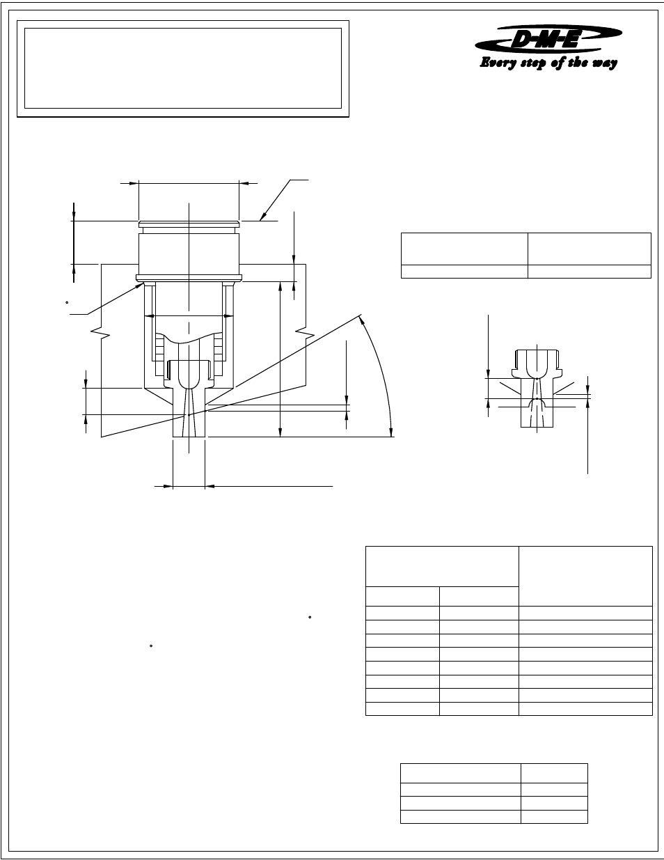
2.001
0.000
+0.001
DIA.
0.
125 MI
N
.
"A
" + B
E
0.
250 MI
N
.
"N"
DIA.
BORE TO FIT TIP
"("T" DIA.) +0.0005 / -0.0000
0.
375 MI
N
.
A
FTE
R CUT
0.
375 MI
N
.
A
FTE
R CUT
0.
080 MI
N
.
3
0
.0
°
0.
080 MI
N
.
EHA0014
CIA0014
6.750
EHA0015
CIA0015
7.750
Square Coil or Cast-In
"N' Dia. (max.)
"N' Dia. (min.)
Square Coil or Cast-In
1.625
1.437
BE="A" dimension x 0.00000633 x (Nozzle set point temperature - 68
5.750
CIA0013
To compensate for the nozzle's growth when heat is applied, the linear
expansion of the nozzle (BE) at a given temperature must be added
to the nominal "A" dimension. The formula
08-08
See material manufactures literature for further information regarding material to be molded.
when selecting small gate diameters. High injection rates may require larger gates due to shear heat build up (e.g. high weight thin wall applications).
requirements, gate vestiage, wall thickness and configuration of part to be molded. Situations requiring high injection velocities must be considered
For selection of gate diameter it is important to take into consideration the materials flow characteristics, shear rate of resin, molding conditions, fill time
SPRUE GATE NOZZLE
Before installing a Extended Sprue Gate Nozzle, it is important to take
NOTE: Nozzle Assembly requires Nozzle Sub-assembly and Tip-assembly.
boring depth (dimension "A" + BE).The tip of the nozzle will now be
flush with cavity line.
Formula for determining this expansion factor is as follows:
Square Coil Heaters and Cast-In Heaters are supplied with 2"
below shows how to figure
prestripped 36" long leads.
INSTALLATION DATA
follow the information below
REFER TO : MINI PRINT # 1800
NOTE: Dimensions are shown in Inches.
NOTE:
SPRUE GATE TIP SUB-ASSEMBLY
the nozzle's expansion factor into consideration. For best results, please
Heaters are 240 VAC.
1 T/C lead is BLACK and positive (+)
2 power leads are Multi Color. 1 ground lead is GREEN.
Thermocouple is "J" Type. Thermocouple is supplied with 36" leads.
1 T/C lead is WHITE and negative (
iron (magnetic).
-
)
constantan (non-magnetic).
Thus "A" + BE will be 3.008
F:
BE = 3 x 0.00000633 x (500 - 68) = 0.008
be necessary to obtain an empirical factor.
MACHINING DIMENSIONS
based on mold configurations and cooling factor. In some instances it may
Note:
ESG3/IS
ME-0741-PS-554-D
The above information is only given as an example. variations may occur
temperature of 500
CHAMFER
WIRING INFORMATION
375 SERIES EXTENDED
MANIFOLD LINE
0.030 X 45
EXAMPLE: Given a 3 inch "A" dimension, with a nozzle set point
F).
NOZZLE SUB-ASSEMBLY
CATALOG NUMBER
"A" DIMENSION
FOR NOZZLE ASSEMBLY
SQ.COIL HTR. CAST-IN HTR.
EHA0008
CIA0008
2.750
EHA0009
CIA0009
3.250
EHA0010
CIA0010
3.750
EHA0011
CIA0011
4.250
EHA0012
CIA0012
4.750
EHA0013
CATALOG NUMBER
"T" DIA.
EHT0019
0.500
EHT0020
0.750
EHT0021
1.000