DME 625 Series Ring Gate Nozzle User Manual
Series 625 ring gate nozzle, Machining & installation data
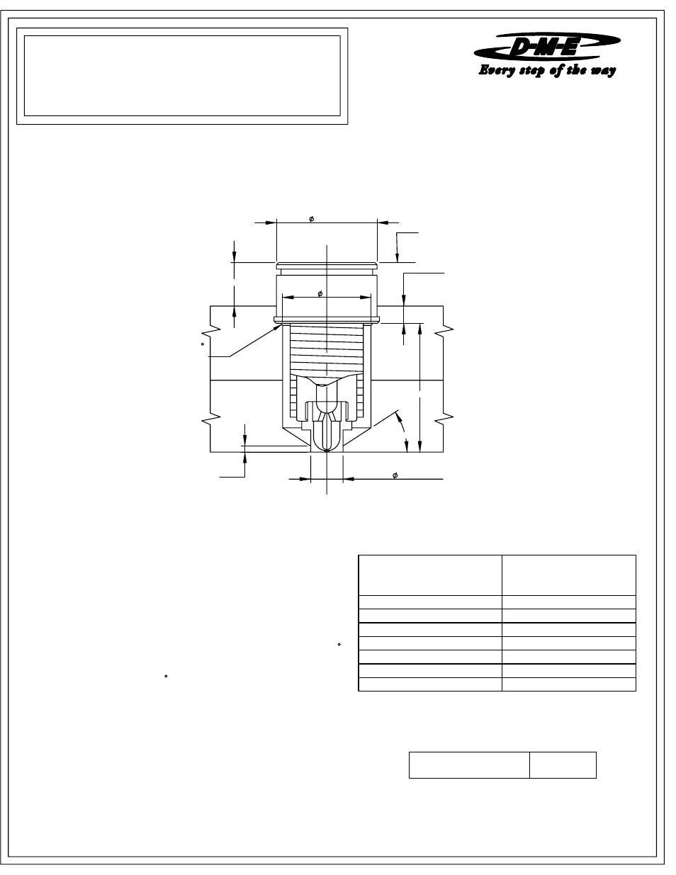
3.001
0.000
+0.001
0.125 MIN.
0.250 MIN.
1.0005
0.0000
+0.0005
2.12
0.080
30°
"A" + BE
0.03 X 45
CHAMFER
MANIFOLD LINE
based on mold configurations and cooling factor. In some instances it may
ME-0741-PS-991-D
RG6/IS
SERIES 625
RING GATE NOZZLE
MACHINING &
INSTALLATION DATA
NOTE:
Before installing a Ring Gate Nozzle, it is important to take the
nozzle's expansion factor into consideration. For best results, please
follow the information below
RING GATE TIP SUB-ASSEMBLY
NOTE: Nozzle Assembly requires Nozzle Sub-assembly and Tip-assembly.
To compensate for the nozzle's growth when heat is applied, the linear
expansion of the nozzle (BE) at a given temperature must be added
to the nominal "A" dimension. The formula below shows how to figure
boring depth (dimension "A" + BE). The tip of the nozzle will now be
flush with cavity line.
Formula for determining this expansion factor is as follows:
Thus "A" + BE will be 3.008
BE="A" dimension x 0.00000633 x(Nozzle set point temperature - 68 F).
EXAMPLE: Given a 3 inch "A" dimension, with a nozzle set point
temperature of 500 F:
BE = 3 x 0.00000633 x (500 - 68) = 0.008
Note: The above information is only given as an example. variations may occur
be necessary to obtain an empirical factor.
NOTE: Dimensions are shown in Inches.
EHA 0016
4.000
EHA 0017
5.000
EHA 0018
6.000
EHA 0019
7.000
EHA 0020
8.000
EHA 0021
9.000
CATALOG NUMBER
EHT 0040
EHA 0022
10.000
08-08
NOZZLE SUB-ASSEMBLY
CATALOG NUMBER
"A" DIMENSION
FOR NOZZLE ASSEMBLY