Resolver module (fmir01), Variable pulse ldt module (fmip01) input option v1 – AMETEK 2110 Shut Height Monitor User Manual
Page 18
Installation and Programming Manual
14
Chapter 3: Mounting and Wiring
15
Installation and Programming Manual
Chapter 3: Mounting and Wiring
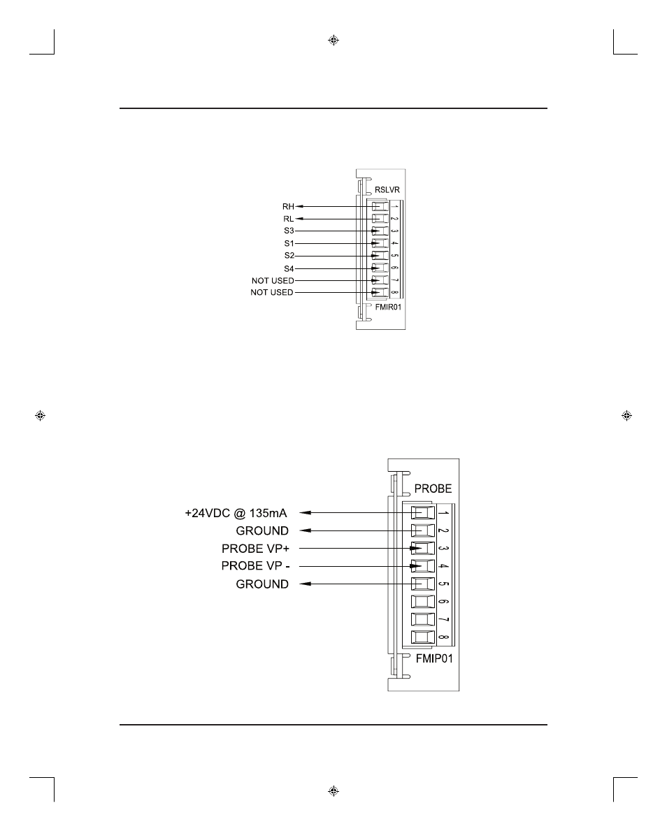
Resolver Module (FMIR01)
The resolver module has an eight-position connector. (See Figure 3-6). The terminal wire size
for all positions is No. 22-12 AWG. Terminal 7 and 8 are not used.
Figure 3-6 Resolver Pinout Diagram
Variable Pulse LDT Module (FMIP01) Input Option V1
The variable pulse LDT module has an eight-position connector. It is only necessary to connect
your LDT to positions 1 through 4. (See Figure 3-7). Positions 1 and 2 provide +24 VDC to
power the LDT. Positions 3 and 4 are used for the LDT’s pulse-width output signals. These
signals comprise an RS-422 differential input. Positions 5-8 are provided for future expansion.
The terminal wire size for all positions is No. 22-12 AWG. This module should only be used
with Gemco LDT model 951VP-2110 tranducers.
Figure 3-7 Variable Pulse LDT Pinout Diagram Input Option V1
T13692 chapter 3.indd
3/17/04, 6:31 AM
14