Wiring, Controller module (fmmp01), Relay output module (fmor01) – AMETEK 2110 Shut Height Monitor User Manual
Page 16
Installation and Programming Manual
12
Chapter 3: Mounting and Wiring
13
Installation and Programming Manual
Chapter 3: Mounting and Wiring
This section contains pinout diagrams for each module. System wiring diagrams follow.
Controller Module (FMMP01)
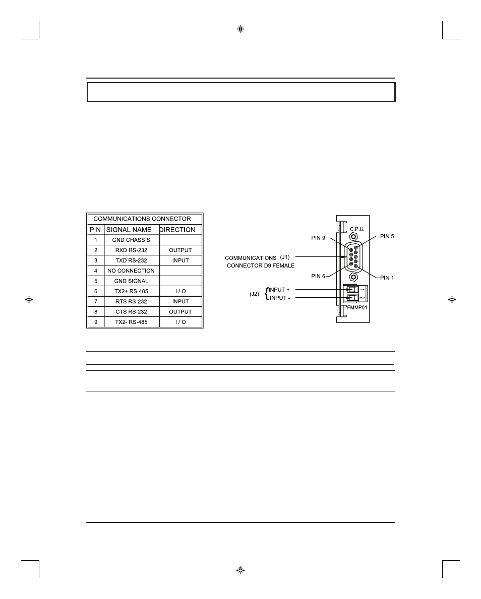
The controller has two connectors: a D9 connector (J1) for RS-232 and RS-485 serial
communications, and a program lockout connector (J2) intended for a keyswitch. (See Figure
3-3). Making connections to both connectors is optional. However, the program lockout
connector must be jumpered to allow the unit to enter program mode. J2’s input rating is +5
VDC maximum dry contact or open collector (drain) only. Actuation voltage must be less than
+1.0 VDC at 0.2 mA. The terminal wire size is No. 22-12 AWG.
Figure 3-3 Controller Pinout Diagram
NOTE: (J2) program lockout connector.
NOTE: The controller’s program lockout connector (J2) must be jumpered to allow the unit
to enter program mode.
Relay Output Module (FMOR01)
The relay output module contains an upper and lower limit relay. Each relay contains a N.O.
contact pair and a separate N.C. contact pair. (See Figure 3-4). Each relay contact rating is 8
amps, 250 VAC, 30 VDC, 1/4 HP 125, 250 VAC. It is recommended that you connect these
relays to the ram adjust motor control circuit to prevent movement beyond the programmed
upper and lower limits. The terminal wire size is No. 22-12 AWG.
3.2: Wiring
T13692 chapter 3.indd
3/17/04, 6:31 AM
12