Figure 4, Bottom of transmitter – Vaisala WXT520 User Manual
Page 23
Chapter 2 __________________________________________________________ Product Overview
VAISALA_______________________________________________________________________ 21
0803-029
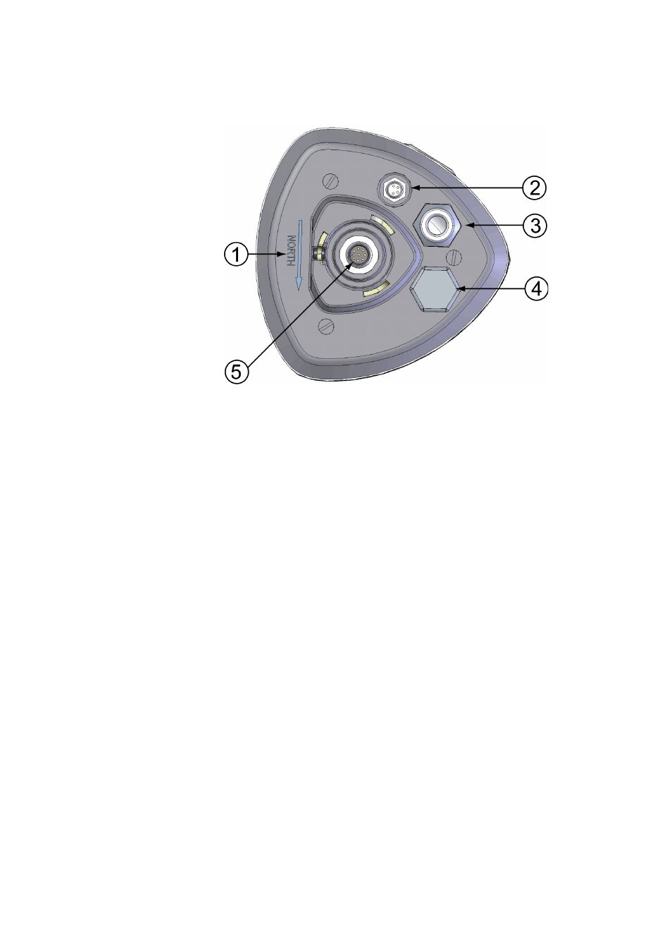
Figure 4
Bottom of Transmitter
The following numbers refer to
:
1
=
Alignment direction sign
2
=
4-pin M8 connector for Service Port
3
=
Water tight cable gland (optional, included in the Bushing and
Grounding Kit)
4
=
Opening for cable gland (if unused, cover with a hexagonal
plug)
5
=
8-pin M12 connector for power/datacom cable (optional)