Table 73, Parameters for the open command – Vaisala Hydromet Data Collection Platform User Manual
Page 335
Chapter 5 __________________________________________ Configuring TCP/IP-Based Telemetry
VAISALA______________________________________________________________________ 333
9.
To monitor different command sequences, check the Extra op.
Info to COM0 or Debug output option when configuring a
device. This enables the device control software to output various
status information to the fixed RS-232 port, that is, to COM0. For
example, you can monitor what is sent to the modem and how it
responds. The printout includes additional internal debug data. The
output is sent only when the service connection is closed.
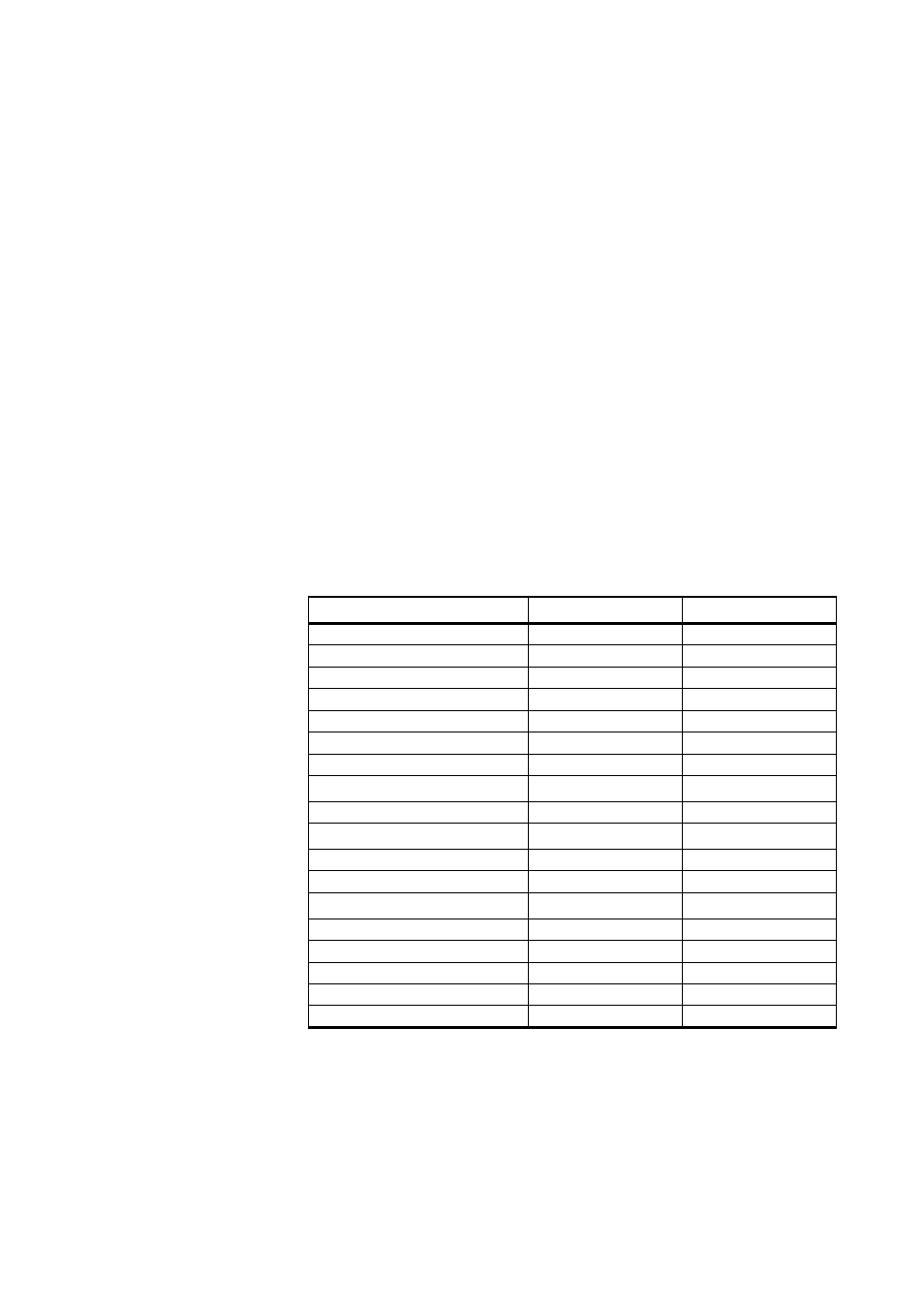
10. To send the AT commands manually, the command interface of the
modem can be directly accessed. To control the modem directly,
open the service connection to the QML logger. For example,
when the device is connected to the first DSU232 communication
port at the module place MOD1, type open DSU232_0_0. To
terminate this operation, type close. While the direct connection to
the modem or sensor is open, any automatic operation through the
connected port is blocked. Typical parameters for the open
command are presented in
. Information
concerning the correct connector can be obtained in Lizard in the
I/O Connections frame of the Equipment view.
Table 73
Parameters for the Open Command
Connector in Lizard
Parameter
Alias
COM0
COM0
COM0
COM1
COM1
COM1
DMX501 (MOD1/1)
DMX501_0
MOD1
DMX501 (MOD2/1)
DMX501_1
MOD2
DSI485A (MOD1/1)
DSI485_0
MOD1
DSI485A (MOD2/1)
DSI485_1
MOD2
DSI486 (MOD1/1)
DSI485_0_0
MOD1_2
DSI486 (MOD1/2)
DSI486_0_1
1
1. With the dual RS-485 module, the RS-232 connection is possible only to
the channel B on the module, and thus the last number is 1.
MOD1_1
DSI486 (MOD2/1)
DSI486_1_0
MOD2_2
DSI486 (MOD2/2)
DSI486_1_1
1
MOD2_1
DSI486SDI (MOD1/3)
DSI486SDI_0
MOD1_3
DSI486SDI (MOD2/3)
DSI486SDI_1
MOD2_3
DSU232 (MOD1/1)
DSU232_0_0
2
2. With the RS-232 and dual RS-485 modules, the number between the
underline characters stands for the module place, that is, MOD1 or MOD2,
and the last number for the channel on that particular module.
MOD1_1
DSU232 (MOD1/2)
DSU232_0_1
MOD1_2
DSU232 (MOD2/1)
DSU232_1_0
MOD2_1
DSU232 (MOD2/2)
DSU232_1_1
MOD2_2
DSU232SDI (MOD1/3)
DSU232SDI_0
MOD1_3
DSU232SDI (MOD2/3)
DSU232SDI_1
MOD2_3