DAVIS Anemometer Transmitter Kit Installation User Manual
DAVIS Thermometers
Product # 6330
A
N E M O M E T E R
T
R A N S M I T T E R
K
I T
I
N S T A L L A T I O N
M
A N U A L
This manual describes how to install the Anemometer Transmitter Kit for Wire-
less Vantage Pro
TM
. The kit enables you to connect the anemometer from your
Integrated Sensor Suite (ISS) to its own transmitter, so it can be located away
from the ISS and communicate directly with your console/receiver.
C
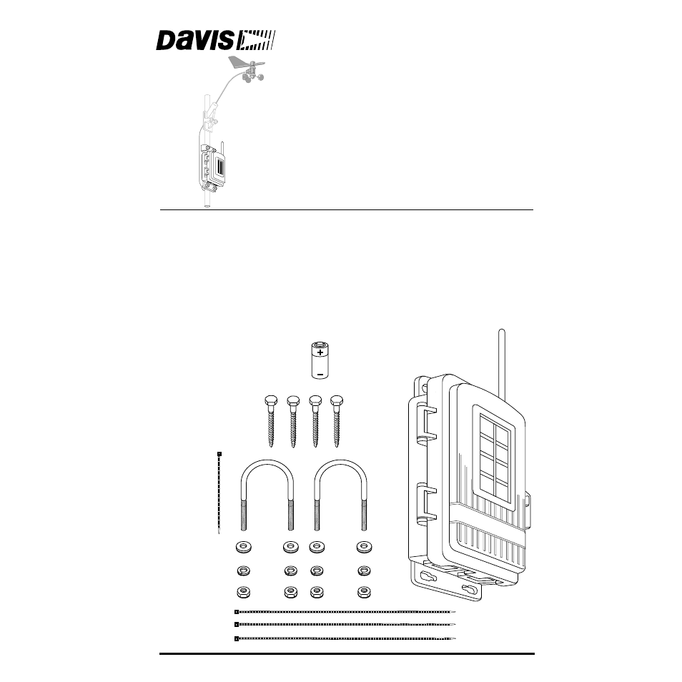
OMPONENTS
The Anemometer Transmitter Kit includes the following components and
mounting hardware:
1/4" Flat Washers
1/4" Lock Washers
1/4" Hex Nuts
3-Volt
Lithium
Battery
U-Bolts
1/4" x 1-1/2" Lag Screws
8" Cable Ties
4" Cable Tie
Transmitter Shelter
Table of contents
Document Outline
- This manual describes how to install the Anemometer Transmitter Kit for Wireless Vantage ProTM. T...
- Components
- Tools for Setup
- Installation Steps
- Removing the Anemometer from its Current Location
- This step assumes that your ISS is already mounted. If it is in a high location such as a rooftop...
- Disconnecting Anemometer from ISS Transmitter
- Reassembling Radiation Shield
- 1. Slide the two open plates over the threaded studs.
- 1. Remove the black rain collector cone from its base by rotating cone counter-clockwise until it...
- 2. Using an adjustable wrench or 7/16" wrench, remove the hex nuts and washers holding the anemom...
- 3. Remove the hex nuts and washers holding the rain collector side on the pole.
- 4. Using the washers and hex nuts, fasten the rain collector side back onto the pole.
- 5. Put the rain collector cone back on.
- If Your Anemometer is Mounted by Itself
- Preparing the Anemometer Transmitter
- 1. Insert the 3-volt lithium battery into the battery holder, matching the “+” sign on the batter...
- 2. Push the end of the anemometer cable up through the square black grommet into the transmitter ...
- 3. Plug the end of the anemometer cable into the receptacle labeled “WIND” on the SIM.
- 4. Using the 4" black plastic cable tie provided, secure the anemometer cable inside the shelter.
- 5. Locate the DIP switches. You will work with them during the next installation step.
- 1. Insert the 3-volt lithium battery into the battery holder, matching the “+” sign on the batter...
- Sensor Interface Module on Anemometer Transmitter
- ID Code
- Switch 1
- Switch 2
- Switch 3
- DIP Switches in Top-right Corner of SIM (Illustration has been enlarged for clarity)
- Setting Console/Receiver(s) to Same ID
- 1. Put your console into Setup Mode — press and hold the DONE key and press the DOWN arrow key.
- 2. Press the DONE key to move on to Screen 2: Selecting Transmitters.
- 3. Press the LEFT or RIGHT arrow key, or the STATION key, to scroll through transmitter IDs.
- 4. Press the GRAPH key to change the type of station assigned to that transmitter ID.
- 5. To exit Setup Mode, press and hold the DONE key.
- Viewing Current Wind Data
- If You Do Not See Current Wind Readings
- TEST mode
- 1. The DIP switches were not correctly set on the transmitter.
- Choosing a Location for the Anemometer Transmitter
- Testing Transmission from Proposed Location
- Mounting the Anemometer Transmitter
- Mounting Anemometer on a Pole
- Mounting Anemometer on a Vertical Surface
- Mounting Transmitter Shelter on a Pole
- Mounting transmitter Shelter on a Post
- DIP Switches in Top-right Corner of SIM (Illustration has been enlarged for clarity)