Sensor interface module on anemometer transmitter, Setting the transmitter id – DAVIS Anemometer Transmitter Kit Installation User Manual
Page 5
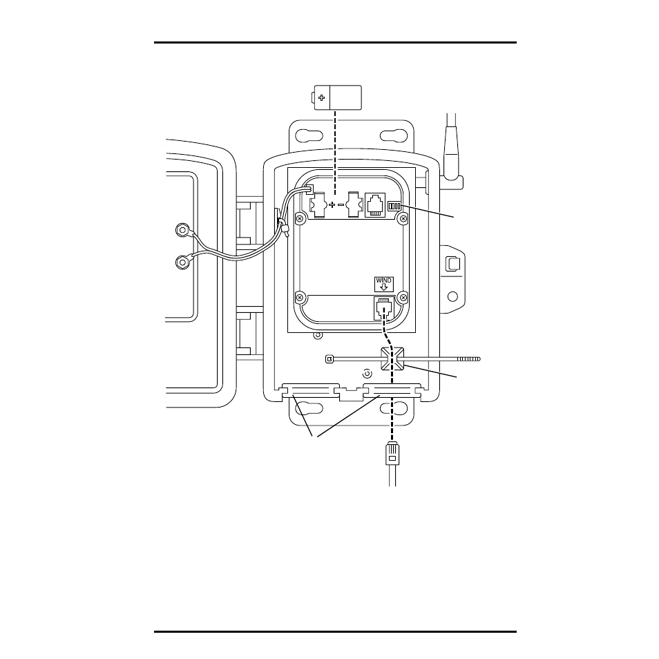
Setting the Transmitter ID
Page 5
5. Locate the DIP switches. You will work with them during the next installation step.
S
ENSOR
I
NTERFACE
M
ODULE
ON
A
NEMOMETER
T
RANSMITTER
S
ETTING
THE
T
RANSMITTER
ID
Each wireless transmitting station must be set to one of eight transmitter IDs.
DIP switches #1, 2 and 3 on the SIM allow you to control the ID — the “chan-
nel” the station will transmit on. (DIP switch #4 is used for transmission test-
ing, not for transmitter ID.)
The transmitter and receiver communicate with each other only when
both
are set to
the same ID.
3-Volt
Lithium Battery
DIP Switches
Cable Tie
Mount
Cable Tie
Anemometer
Cable
Square Black Grommets
See also other documents in the category DAVIS Thermometers:
- Envoy8X Getting Started Guide (16 pages)
- Vantage Pro2 Long Range Repeater Installation Addendum (16 pages)
- Wireless Temperature Station (6372) Installation Manual (12 pages)
- Solar Power Kit For Vantage Weather Stations and Envoy8X (8 pages)
- Energy EnviroMonitor: Console (63 pages)
- EZ-Mount Installation (16 pages)
- Gro/Energy/Health Installation (24 pages)
- GroWeather Console (65 pages)
- GroWeather/EnviroMonitor: Systems Installation (24 pages)
- Health EnviroMonitor: Console (60 pages)
- Anemometer (7911, 7914) (8 pages)
- Rain Collector II for GroWeather, EnviroMonitor, Weather Monitor and Wizard (16 pages)
- Sensor - UV for GroWeather or EnviroMonitor (16 pages)
- Solar Radiation Sensor for GroWeather and EnviroMonitor (16 pages)
- Temperatur/Humidity Sensor for GroWeather, EnviroMonitor, & Weather Monitor (12 pages)
- Temperature Sensor/Probe for GroWeather, EnviroMon., Weather Monitor/Wizard (4 pages)
- GroWeatherLink Software (108 pages)
- GroWeatherLink/ET Data Logger (2 pages)
- Short-Range Modem Pair: Perception, GroWeather, EnviroMon., Monitor, Wizard (8 pages)
- Alarm Output Module (16 pages)
- Cable Coupler Kit (4 pages)
- Cable Crimp-Type Splice Connector (4 pages)
- Complete System Shelter (12 pages)
- Fan-Aspirated Radiation Shield (24 pages)
- Grounding Kit (4 pages)
- Interface Cable Adapter Module (8 pages)
- Mounting Pole Kit Installation (4 pages)
- Mounting Tripod Kit (8 pages)
- Multi-purpose Shelter (12 pages)
- Radiation Shield (7714) (16 pages)
- Radio Surge Protector (4 pages)
- Rain Collector Heater (12 pages)
- Rain Collector Shelf: GroWeather, EnviroMonitor, Weather Monitor & Wizard (8 pages)
- Second Solar Panel for EZ-Mount Solar Power Kit (4 pages)
- Sensor Mounting Arm for GroWeather, EnviroMonitor, Weather Monitor & Wizard (16 pages)
- Sensor Tilting Bracket for GroWeather or EnviroMonitor (8 pages)
- Shelter Heaters (12 pages)
- Solar Power Kit for Non-Vantage Pro Stations (16 pages)
- Surge Protector (2 pages)
- Surge Protector Shelter - Large (8 pages)
- Surge Protector Shelter - Small (4 pages)
- Terminal Box for sensors/interface module, communication lines: GroWeather (8 pages)
- WeatherLink for Windows 4.0 (116 pages)
- WeatherLink Getting Started Guide (20 pages)
- WeatherLink Mac OS X Getting Started Guide (16 pages)