JKS BSE251 User Manual
Page 4
JKSBSE251
JKS Hydraulic Bump Shocks Installation
4 Page
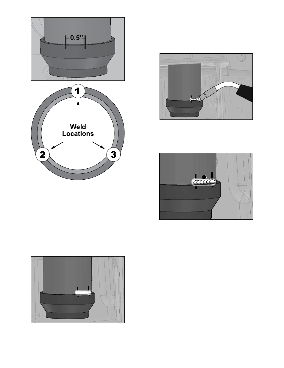
Remove Jounce Adapter (C) from Chassis Tube
(D) and locate the weld location markings on both
components.
Remove the zinc plating from the marked locations
on the Jounce Adapter (C).
HINT: Emory cloth or a
suitable stripping tool is useful for removal of coat-
ings. Make sure bare metal is completely exposed
and free of contaminants to ensure proper weld
penetration.
Reposition the Jounce Adapter (C) on the Chassis
Tube (D), making sure the locations prepped for
welding are in alignment.
Tack weld the Jounce Adapter (C) to the Chassis
Tube (D) at each location. Make sure the adapter
has remained fully seated against the tube before
proceeding.
Next, weld a 1/2” long bead over each tack weld
to ensure the Jounce Adapter (C) remains secured
to the Chassis Tube (D).
HINT: As long as you
achieve proper weld penetration on the adapter
and spring retainer, it is not necessary to weld
around the entire perimeter.
Allow the welded sections to cool and then drill a
3/8” hole through the Chassis Tube (D) immedi-
ately above one of the welds.
HINT: The purpose
of the hole is to facilitate the evacuation of any
moisture that may collect inside the tube.
To prevent corrosion, it will be necessary to paint
all exposed surfaces on the Jounce Adapter (C)
and Chassis Tube (D). Prepare for painting by
thoroughly cleaning any dirt, debris or deposits
from the area.
HINT: A clean piece of emory cloth
or equivalent is useful for preparing the area to be
painted.
Completely cover the exterior of the Jounce
Adapter (C) and all exposed metal on the Chassis
Tube (D) with satin black spray paint. Protect inner
threads of adapter from overspray.
5. INSTALL BUMP SHOCK ASSEMBLY
Apply anti-seize lubricant to internal threads of
Jounce Adapter (C) and Bump Shock Nut (B).
Completely thread the Bump Shock Nut (B) onto
Bump Shock Assembly (A).
Thread Bump Shock Assembly (A) into Jounce
Adapter (C) as far as possible.