JKS BSE251 User Manual
Page 3
JKSBSE251
JKS Hydraulic Bump Shocks Installation
Page 3
Using the reference hole illustrated above as
the center point, mark a 2.5” diameter circle on
the bottom of the chassis rail. This indicates the
material to remove in order to accommodate the
supplied Chassis Tubes (D).
Transfer the markings from the bottom of the chas-
sis onto the outer side of the frame rail.
If necessary, adjust the markings on the chassis to
ensure they are in alignment with the landing pad
on the axle at full suspension compression.
Carefully cut along the marked lines using an
appropriate cutting tool. Only remove as much
material from the chassis as necessary to accom-
modate the Chassis Tube (D). Always err on the
conservative side when removing material from
the chassis rail. Welding the Chassis Tube in place
will be easiest with a tight fit-up and minimal gaps.
3. WELD CHASSIS TUBE IN PLACE
Position the Chassis Tube (D) in the notched frame
rail and make sure it is properly aligned.
Securely clamp the Chassis Tube (D) in place to
prepare for welding.
Tack weld the Chassis Tube (D) to the frame rail in
several locations to prevent it from shifting during
final welding.
Check the position and alignment of the Chassis
Tube (D) one last time to make sure the Hydraulic
BumpShock will contact the landing pad as intended.
Weld the Chassis Tube (D) to the frame rail until
the gap between them is completely filled. Avoid
overheating frame rail by stopping to allow the
surface to cool off regularly.
3. INSTALL JOUNCE ADAPTER ON
CHASSIS TUBE
Locate the supplied Jounce Adapters (C). The
adapters are zinc plated from the factory to pre-
vent corrosion. In preparation for welding, a small
amount of plating must be removed to ensure the
areas to be welded are clean.
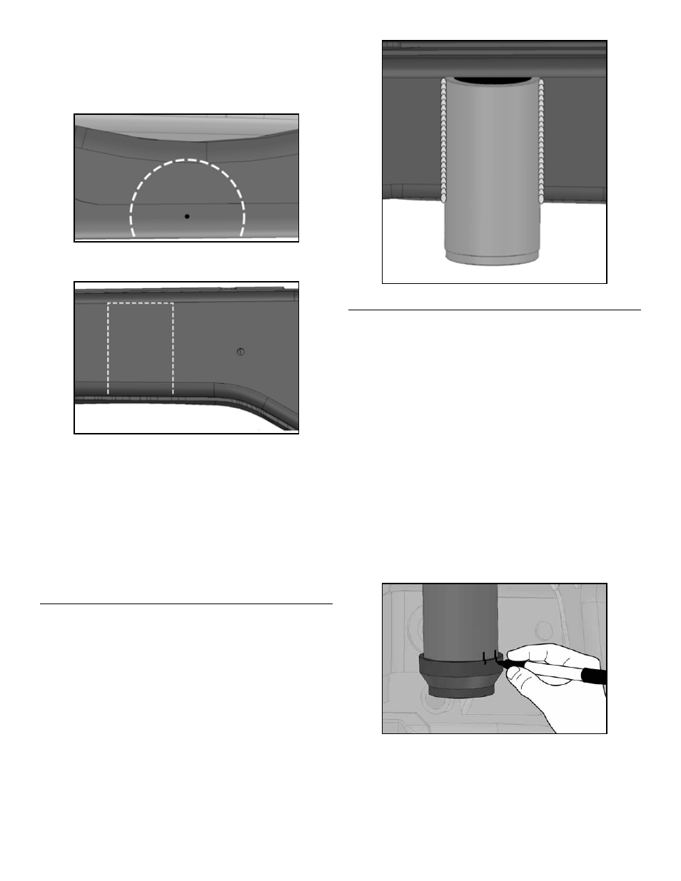
Slide the enlarged (non-threaded) end of the
Jounce Adapter (C) onto the Chassis Tube (D) until
fully seated. Hold in position while completing the
next step.
Mark the perimeters of the Chassis Tube (D) AND
the Jounce Adapter (C) where they meet at three
(3) locations that are accessible for welding. Each
weld location should be at least 1/2” in length
and spaced evenly apart.
HINT: A felt tip marker
or similar marking tool is useful for marking weld
locations.
HINT: A pair of vertical lines spaced 0.5” apart is
used to mark each weld location.