Parts, Installation – JKS BSE251 User Manual
Page 2
JKSBSE251
JKS Hydraulic Bump Shocks Installation
2 Page
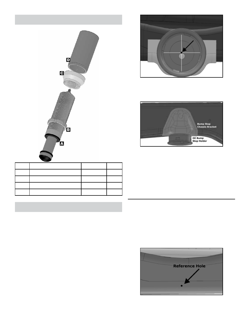
Parts
Description
Part #
QTY
A
Bump Shock Assembly
RFC/BS02
2
B
Bump Shock Nut
RFC/SN50
2
C
Jounce Adapter
03154
2
D
Bump Shock Chassis Tube
03155
2
Installation
1. PREPARE VEHICLE FOR CHASSIS
MODIFICATIONS
Remove rear track bar, shocks, coil springs, and
any other components that prevent you from ac-
cessing the factory rear bump stop holders.
HINT:
You will need to access this part of the chassis
from multiple directions so make sure you have
plenty of freedom to work.
Drill a small hole exactly through the center of
the factory upper bump stop holders and into the
chassis. Make sure drill is square with chassis.
HINT: This provides a reference point to work from
during installation, as center of BumpShock must
remain at the same centerline as the factory bump
stop.
Remove the factory upper bump stop holders from
the chassis brackets.
HINT: The bump stop holder
is welded to the chassis bracket and must be cut
free.
Next remove the factory bump stop brackets from
the chassis.
HINT: The bracket is welded to the
chassis along its perimeter. It must be carefully
removed without gouging or otherwise damaging
the chassis.
With the bump stop holders and brackets re-
moved, clean the chassis of any remaining weld
material until smooth.
2. FRENCH CUT CHASSIS
The chassis rails must be frenched to accept the supplied
Chassis Tubes (D). When executed correctly, the Hydrau-
lic BumpShock will be positioned on the same centerline
as the OE bump stop holder (identified by the previously
drilled reference hole). Also, the BumpShock must contact
the center of the landing pad on the axle when the suspen-
sion is compressed.