Pdu a, Pdu b, Pdms – HP 6400.8400 Enterprise Virtual Array User Manual
Page 22: Pdu a pdu b
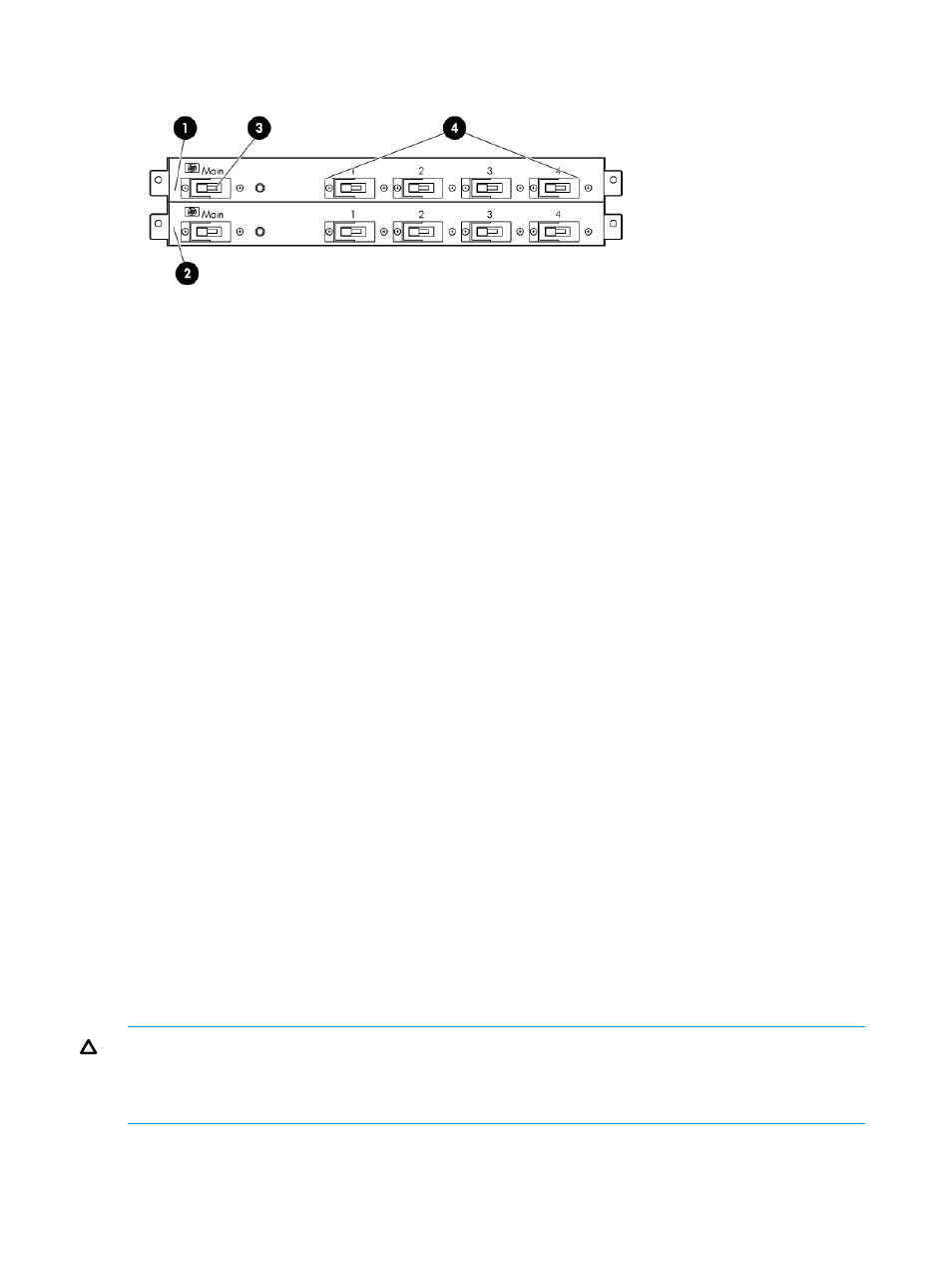
Figure 17 Dual PDU—rear view
3. Main circuit breaker
1. PDU B
4. Circuit breakers
2. PDU A
PDU A
PDU A connects to AC PDM A1–A4.
A PDU A failure:
•
Disables the power distribution circuit
•
Removes power from from the left side of the rack
•
Disables disk enclosure PS 1
•
Disables the left power supplies in the controllers
PDU B
PDU B connects to AC PDM B1–B4.
A PDU B failure:
•
Disables the power distribution circuit
•
Removes power from the right side of the rack
•
Disables disk enclosure PS 2
•
Disables the right power supplies in the controllers
PDMs
Depending on the rack, there can be up to eight PDMs mounted in the rear of the rack:
•
The PDMs on the left vertical rail connect to PDU A
•
The PDMs on the right vertical rail connect to PDU B
Each PDM has seven AC receptacles. The PDMs distribute the AC power from the PDUs to the
enclosures. Two power sources exist for each controller pair and disk enclosure. If a PDU fails, the
system will remain operational.
CAUTION:
The AC power distribution within a rack ensures a balanced load to each PDU and
reduces the possibility of an overload condition. Changing the cabling to or from a PDM could
cause an overload condition. HP supports only the AC power distributions defined in this user
guide.
22
EVA6400/8400 hardware