Blower module, Battery module, Blower module battery module – HP 6400.8400 Enterprise Virtual Array User Manual
Page 17
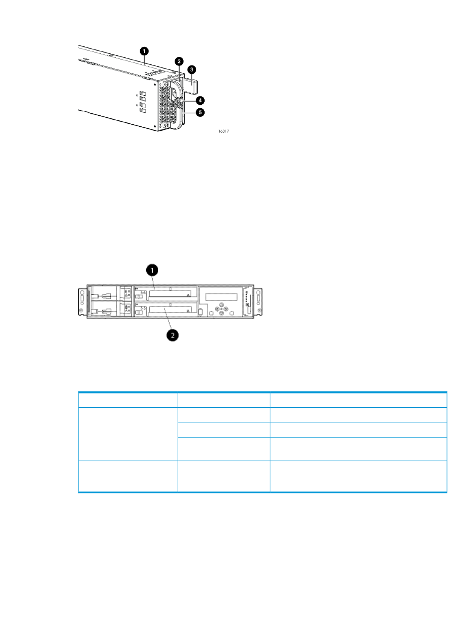
Figure 12 Power supply
4. Status indicator (solid green on—normal operation; solid
amber—failure or no power)
1. Power supply
5. Handle
2. AC input connector
3. Latch
Blower module
Fan modules provide the cooling necessary to maintain the proper operating temperature within
the controller enclosure. If one fan fails, the remaining fan is capable of cooling the enclosure.
Figure 13 Blower module pulled out
2. Blower 2
1. Blower 1
Table 7 Fan status indicators
Description
Fault indicator
Status indicator
Normal operation.
Solid green
Green
Maintenance in progress.
Blinking
Amber is on or blinking, or the enclosure is powered
down.
Off
Fan failure. Green will be off. (Green and amber are
not on simultaneously except for a few seconds after
power-up.)
On
Amber
Battery module
Batteries provide backup power to maintain the contents of the controller cache when AC power
is lost and the storage system has not been shutdown properly. When fully charged the batteries
can sustain the cache contents for to 96 hours. Three batteries are used on the EVA8400 and two
batteries are used on the EVA6400.
illustrates the location of the cache
batteries and the battery status indicators. See
for additional information on
the status indicators.
Blower module
17