Hsv controller cabling – HP 6400.8400 Enterprise Virtual Array User Manual
Page 18
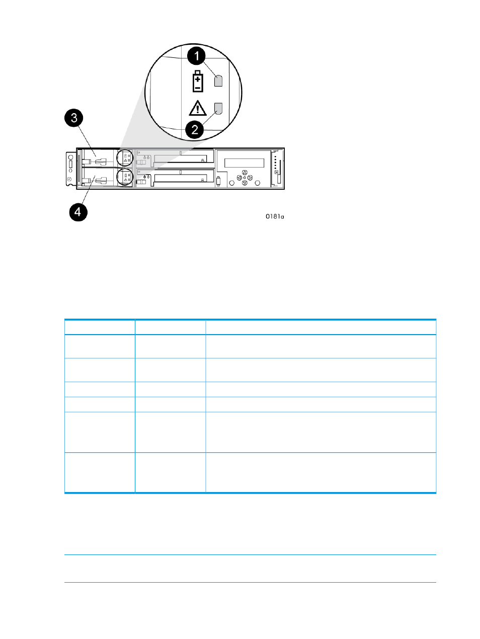
Figure 14 Battery module
3. Battery 0
1. Status indicator
4. Battery 1
2. Fault indicator
The table below describes the battery status indicators. When a battery is first installed, the fault
indicator goes on (solid) for approximately 30 seconds while the system discovers the new battery.
Then, the battery status indicators display the battery status as described in the table below.
Table 8 Battery status indicators
Description
Fault indicator
Status indicator
Normal operation. A maintenance charge process keeps the battery fully
charged.
Off
On
Battery is undergoing a full charging process. This is the indication you
typically see after installing a new battery.
Off
Flashing
Battery fault. The battery has failed and should be replaced.
On
Off
The battery has experienced an over temperature fault.
Flashing
Off
Battery code is being updated. When a new battery is installed, it may
be necessary for the controllers to update the code on the battery to the
Flashing (fast)
Flashing (fast)
correct version. Both indicators flash rapidly for approximately 30
seconds.
Battery is undergoing a scheduled battery load test, during which the
battery is discharged and then recharged to ensure it is working properly.
Flashing
Flashing
During the discharge cycle, you will see this display. The load test occurs
infrequently and takes several hours.
HSV controller cabling
All data cables and power cables attach to the rear of the controller. Adjacent to each data
connector is a two-colored link status indicator.
identifies the status conditions
presented by these indicators.
NOTE:
These indicators do not indicate whether there is communication on the link, only whether
the link can transmit and receive data.
18
EVA6400/8400 hardware