Installing xpak transponders – HP 9000 Virtual Library System User Manual
Page 41
15. A prompt asks if you want to log out. Enter y.
The switch logs off, and the spanning tree is now reconfigured to include the new switch.
16. Repeat this procedure for the remaining Ethernet switches in racks 1 and 3.
NOTE:
After reconfiguring the Ethernet switches, power down the entire VLS system. See
for instructions.
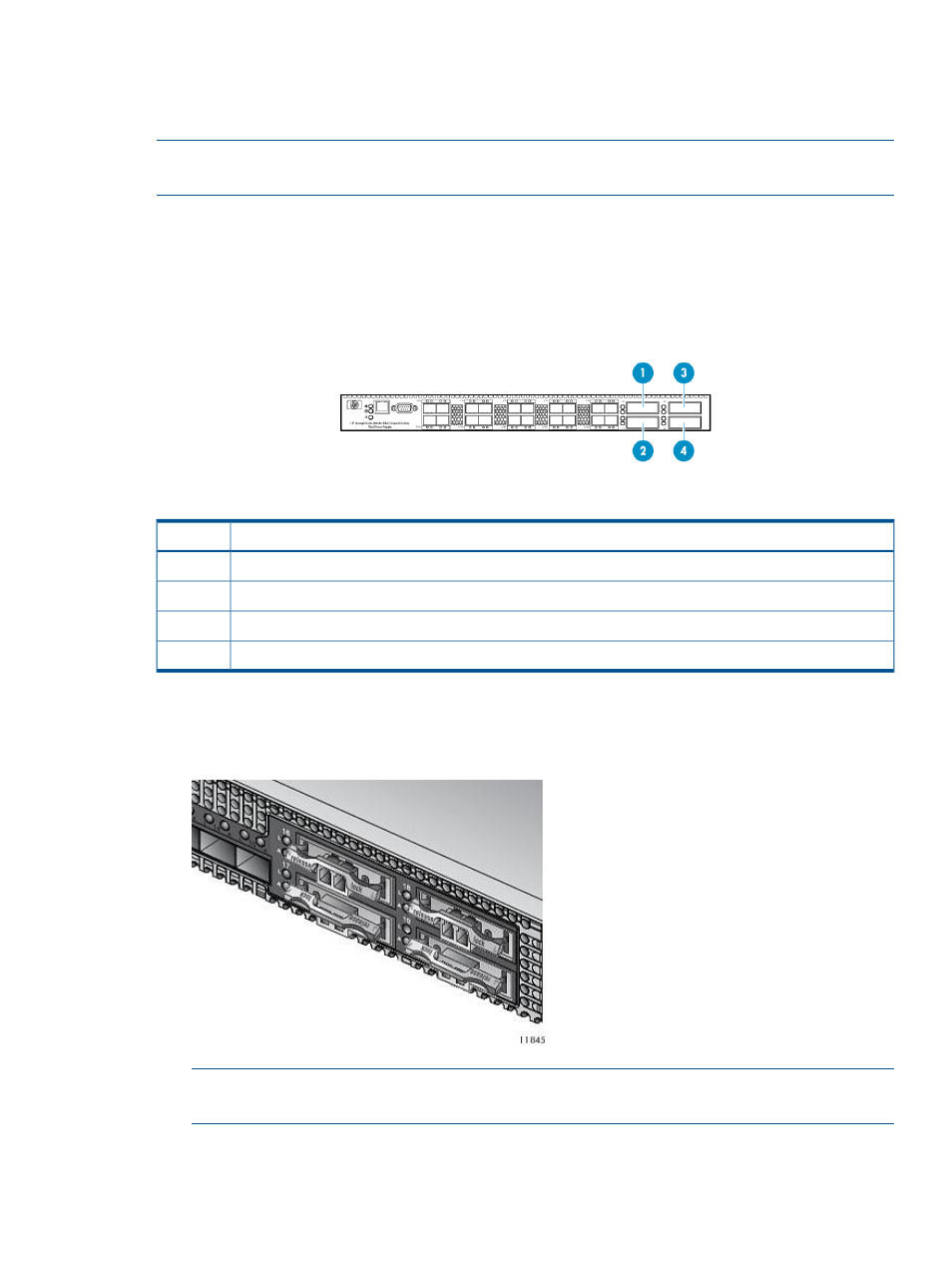
Installing XPAK Transponders
The XPAK transponders (XPAKs) plug into the 10 Gb Fibre Channel ports in the front of the 20–port
Fibre Channel switches. The 20–port Fibre Channel switches are included in the 40–port connectivity
kits.
Description
Item
Fibre Channel port 20
1
Fibre Channel port 21
2
Fibre Channel port 22
3
Fibre Channel port 23
4
1.
Locate four XPAKs supplied in the interswitch link kit contents.
2.
Remove the port covers from ports 16 through 19 on the 20–port Fibre Channel switches.
3.
With the latch in the center position, slide the XPAK into the port until it clicks into place.
NOTE:
Install XPAKs into ports 20 and 22 with the heat sink facing up. Install XPAKs into
ports 21 and 23 with the heat sink facing down.
4.
Move the latch to the locked position, as indicated on the latch.
5.
Repeat steps 2 through 4 for each Fibre Channel switch with the remaining XPAKs.
Installing the VLS9000 Interswitch Link Kit
41