Front panel components, Front panel leds and buttons – HP 9000 Virtual Library System User Manual
Page 197
Status
Description
Item
Off = One of these conditions exist:
•
The port connection is broken.
•
An error occurred that disabled the port.
Green = data is passing through the port.
Port Activity LED (on
bottom for each port)
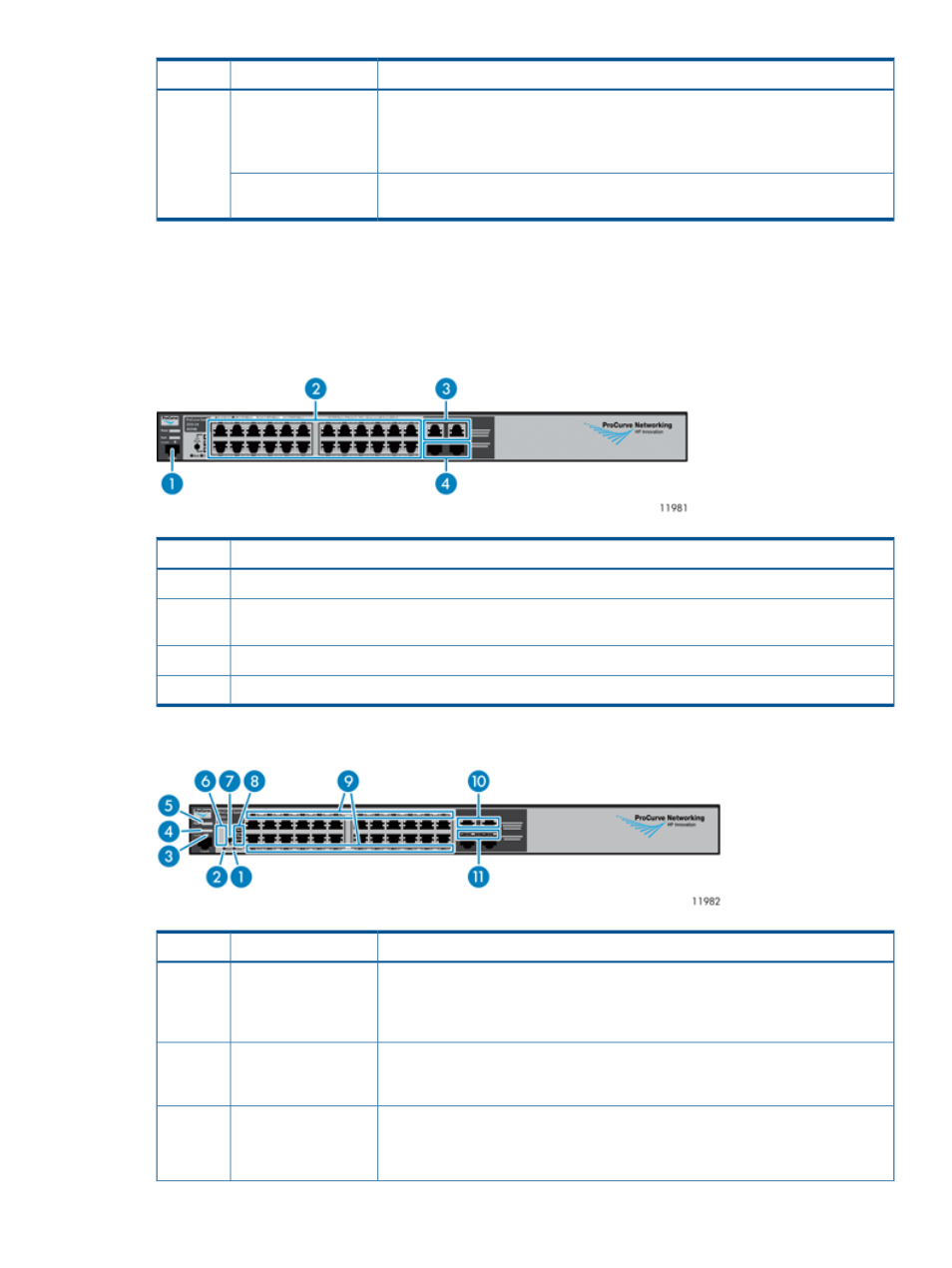
Ethernet Switch 2510–24 Components, LEDs, and Buttons
This section provides images and descriptions of the front and rear panels of the Ethernet Switch
2510–24.
Front Panel Components
Description
Item
Console port
1
10/100Base-TX RJ-45 Ethernet ports 1 through 24
(numbered from left to right, top to bottom)
2
10/100/1000–T dual-personality ports 25 and 26
3
mini—GBIC dual-personality ports 25 and 26
4
Front Panel LEDs and Buttons
Status
Description
Item
When pressed with the Reset button in a specific pattern, any configuration changes
you may have made through the switch console, the web browser interface, and
Clear button
1
SNMP management are removed, and the factory default configuration is restored
to the switch.
Press to reset the switch while it is powered on. This action clears any temporary
error conditions that may have occurred and executes the switch self test. Also
resets all network activity counters to zero.
Reset button
2
Blinking blue = Locate function is active. Firmware controlled, can be set to on or
blinking.
Locator LED
3
Off = Locate function is disabled.
Ethernet Switch 2510–24 Components, LEDs, and Buttons
197