Installing the ethernet switch 2510–24 into a rack – HP 9000 Virtual Library System User Manual
Page 35
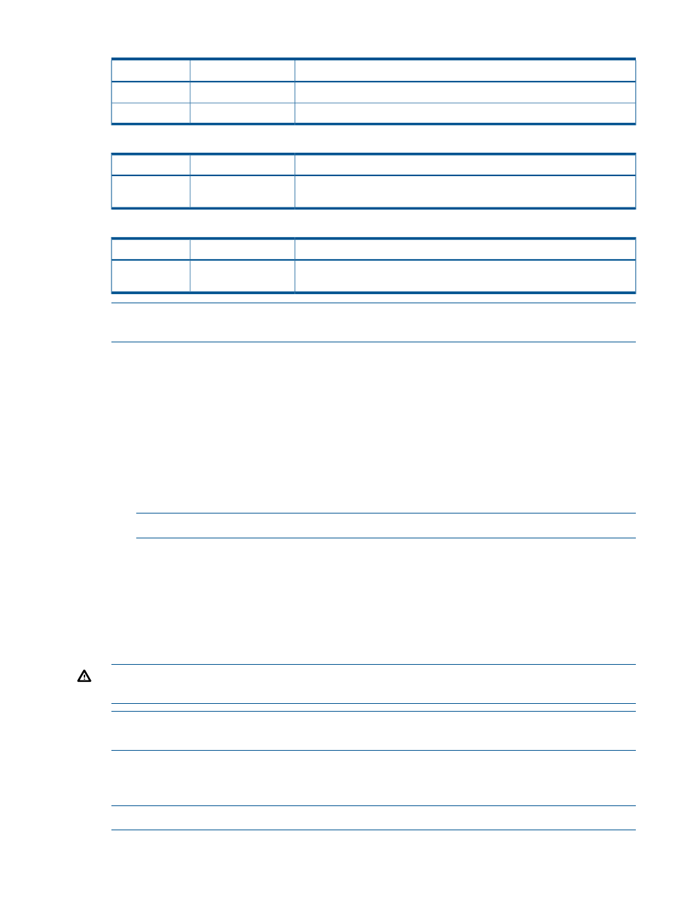
Table 5 Cabling Ethernet Switch #2 (SW2) (continued)
Connects to
Description
Item
Ethernet port of FC switch #2 (FC SW2) via Ethernet cable
Port 23
23
Port 24 of Ethernet switch #1 (SW1) via Ethernet cable
Port 24
24
Table 6 Cabling Ethernet Switch #3, if present (SW1 of a second kit)
Connects to
Description
Item
Ethernet port of RAID Controller 2 of additional base array enclosures via
Ethernet cable
Ports 17–20
17–20
Table 7 Cabling Ethernet Switch #4, if present (SW2 of a second kit)
Connects to
Description
Item
Ethernet port of RAID Controller 1 of additional base array enclosures via
Ethernet cable
Ports 17–20
17–20
NOTE:
Ethernet switch #1 is on the bottom and switch #2 is on the top. If present, Ethernet switch
#3 is on the bottom and switch #4 is on the top.
1.
Connect the Ethernet switches to each other and to the Fibre Channel switches using
and
2.
Connect the Ethernet switches to the nodes and base array enclosures if not already connected.
If installing multiple arrays:
a.
Connect an Ethernet cable from Ethernet switch #1 to RAID controller 2 of additional
arrays in order (array 1, array 2, etc.). Use the switch #1 ports in this order: 20, 17, 18,
15, 16, 13, 14.
b.
Connect an Ethernet cable from Ethernet switch #2 to RAID controller 1 of additional
arrays in order (array 1, array 2, etc.). Use the switch #2 ports in this order: 20, 17, 18,
15, 16, 13, 14.
NOTE:
Each rack supports up to four arrays.
3.
If installing a second connectivity kit in rack 4:
a.
Connect an Ethernet cable from Ethernet switch #3 to RAID controller 2 of additional
arrays in order (array 13, array 14, etc.). Use the switch #3 ports in this order: 19, 20,
17, 18.
b.
Connect an Ethernet cable from Ethernet switch #4 to RAID controller 1 of additional
arrays in order (array 13, array 14, etc.). Use the switch #4 ports in this order: 19, 20,
17, 18.
WARNING!
Do not connect cables to unused ports on Ethernet switch #1 or #2. Doing so could
result in data loss.
NOTE:
Do not secure the Ethernet cables at this time. You will secure them with the Fibre Channel
cables.
Installing the Ethernet Switch 2510–24 into a Rack
VLS9200 Entry-level systems use the Ethernet Switch 2510–24. No other switches are required.
NOTE:
There are no rails associated with this switch.
Installing the Ethernet Switch 2510–24 into a Rack
35