American Power Conversion PDU User Manual
Page 38
Installation Procedures: Wiring Under the Floor
30
150kW InfraStruXure System—Installation and Start-Up
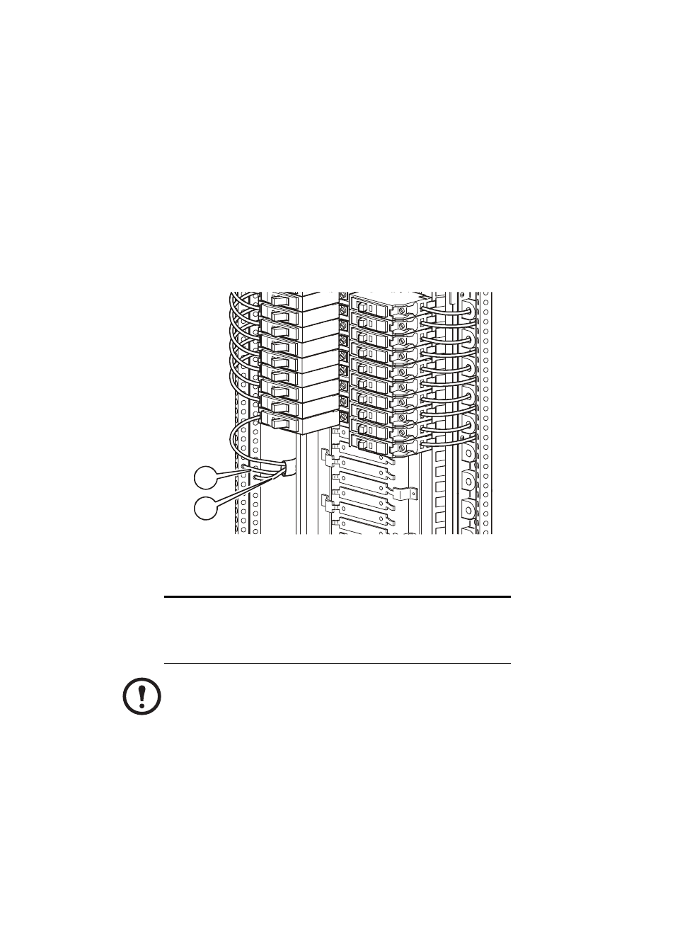
5. At the circuit breaker panel, cut the wires to the proper length, and connect the power cable’s
individual wires:
a. If you have branch current monitoring installed, route each phase conductor through a
current sensor. If it is a three-phase cable, route the L1, L2, and L3 wires through a separate
current sensor.
b. Connect the L1, L2, and L3 wires to the circuit breaker(s). The following illustration shows a
three-phase cable connecting to three single-pole breakers; however, you can also connect a
three-phase cable to a three-pole breaker, or a single-phase cable to a single-pole breaker.
c. Connect the neutral wire to the closest open termination point on the Neutral Bar (N).
d. Connect the ground wire to the closest open termination point on the Ground Bar (G).
The following table provides specific information about connecting to each terminal.
Terminal Torque
Tools
L1, L2, L3
150in-lb (17Nm)
6-mm Allen wrench
G
4–6AWG: 45in-lb (5.0Nm)
Slotted screwdriver
GEC
8AWG: 40in-lb(4.5Nm)
Slotted screwdriver
Note
Any customer-specified, hard-wired, multi-circuit power cable that is
installed by an electrical contractor must be installed with a circuit breaker
which provides both automatic and manual disconnection of all non-grounded
circuit conductors.
G
N