Torque specs and tools required, Gec g l1 l2 l3 – American Power Conversion PDU User Manual
Page 24
Installation Procedures: Connect the Power Source to the PDU
16
150kW InfraStruXure System—Installation and Start-Up
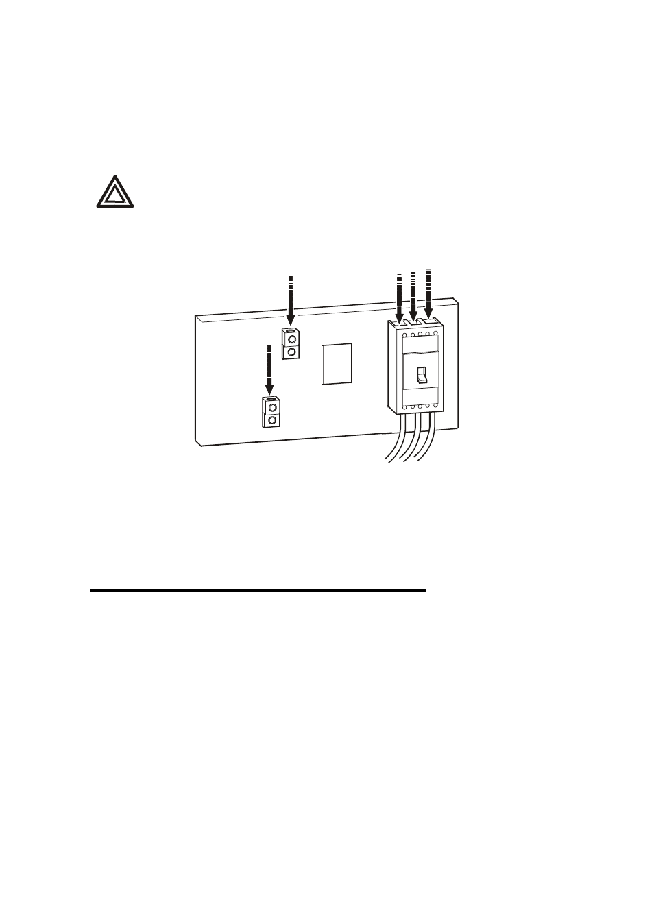
Route the input conductors to the Main Input circuit breaker
Route the input conductors to the Main Input circuit breaker of the PDU and connect the input wiring
according to the lables on the circuit breaker and the following illustration. Refer to the following
table “Torque specs and tools required” for specific information about connecting to each terminal.
3-phase, 3-wire + ground + GEC to building steel
*
Torque specs and tools required
Before connecting to the terminals, verify the torque specs below by checking the specifications on
the Main Input circuit breaker.
C
*
Other types of electrodes may be used if building steel is not available, consult NEC codes for
requirements.
Warning
Connect the conductors to the terminals according to the labels on the terminals.
Use copper conductors only.
GEC
G
L1
L2
L3
Terminal Torque
Tools
L1, L2, L3
150in-lb (17Nm)
6-mm Allen wrench
G
4–6AWG: 45in-lb (5.0Nm)
Slotted screwdriver
GEC
8AWG: 40in-lb (4.5Nm)
Slotted screwdriver