Connect an emergency power off switch, Overview, Contact closure is recommended – American Power Conversion PDU User Manual
Page 25: Connecting the switch, Configuring and testing, Caution
150kW InfraStruXure System—Installation and Start-Up
17
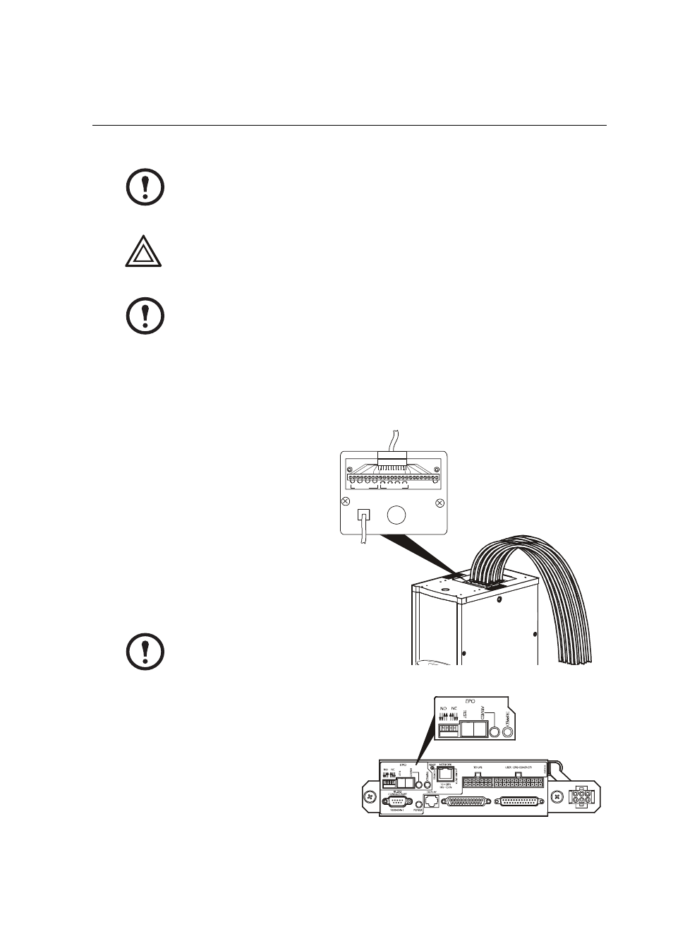
Connect an Emergency Power Off Switch
Overview
Connecting the switch.
The
Emergency Power Off (EPO) switch
connects to the PDU user connection plate.
The figure on the right shows the location
of the user connection plate on the roof of
the PDU. Connect a switch using one of
three following connections:
• Contact closure
• 24VAC
• 24VDC
Configuring and testing.
Configuring and
testing of the switch is done through the EPO
interface on the PDU monitoring unit. The
figure to the right shows the PDU monitoring
unit and the location of the EPO LEDs and
switches.
Note
APC offers an optional InfraStruXure EPO System (EPW9). Contact your APC
sales representative, or visit the APC Web site (www.apc.com) for more
information.
Caution
If you are not connecting an Emergency Power Off switch to the PDU, leave the
Arm/Test rocker switch on the PDU monitoring unit in the Test position.
Note
The PDU monitoring unit provides the EPO function. The purpose of this function
is to activate any shunt trips that are controlled by the PDU monitoring unit. These
shunt trips are on breakers that are part of the power source feeding the PDU. The
PDU breakers do not have any shunt trips.
Note
Contact closure is recommended.
1
2
3
4
AT
S E
N
AT
S 0
AT
S
1
AT
S 2
EPO
Contact
– +
EPO 24V
AC/DC
Contact Inputs
Contact Outputs
USER INTERFACE
© 2001 APC
MADE IN USA