Mirror temperature, Analog outputs – ROTRONIC MBW 373 User Manual
Page 28
24
Mirror Temperature
The mirror of the 373 is equipped with two independent temperature sensors. One is used for
system measurement and control. The wires of the other sensor are brought directly to the back
panel’s Mirror Temperature connector and are for your use. Using this connection, you may
measure the mirror temperature sensor directly without affecting normal system operation.
The wires internal to the 373 are shielded up to the connector. You must be responsible for any
shielding requirements between the connector and your measuring instrument.
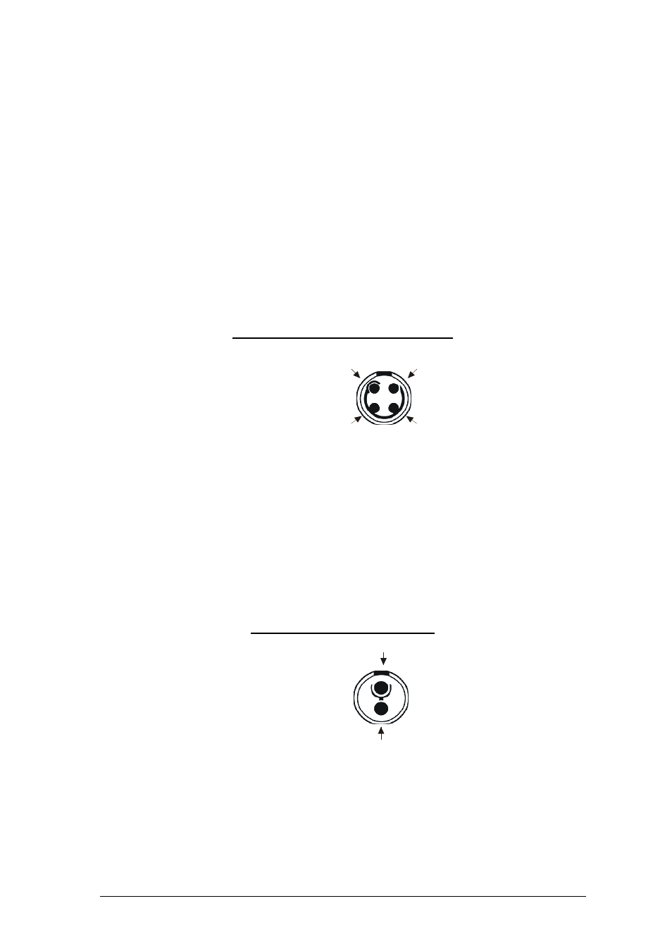
If you wish to make a cable for directly measuring the mirror PRT, the 373 requires a 4 pin
connector, LEMO (www.lemo.ch) part number FGG 1B 304 CLAD 42. When wiring the cable,
note that pin numbering of the socket installed in the back panel starts at the top left corner and
goes counter-clockwise (as viewed from the rear of the unit). When viewing the solder tubs of a
disassembled 4-pin LEMO connector, pin 1 is usually identified with a full or partial circle drawn
around it. After identifying pin 1, follow the line counter-clockwise from pin 1 to all other pins in
succession. Wire the cable according to the following:
Pin Signal Position
1 +I
2 +V
3 -V
4 -I
1
2
3
4
When the 4-pin LEMO connector is properly assembled, you will notice that the red dot of the
connector housing will be aligned at the top between pins 1 and 4.
Analog Outputs
Analog outputs are used for connection of external voltmeters or chart recorders. The analog
outputs are independently configurable. If you wish to make your own cables, the 373 requires a
2 pin connector, LEMO (www.lemo.ch) part number FGG 1B 302 CLAD 42. When viewing the
solder tubs of a disassembled 2-pin LEMO connector, pin 1 is usually identified with a full or
partial circle drawn around it. Pin 2 should have no identifier. Wire the cable according to the
following:
Pin Signal Position
1 +V
2 -V
2
1
When the 2-pin LEMO connector is properly assembled, you will notice that the red dot of the
connector housing will be aligned at the top directly above pin 1.