2 installation of technology units in the sk 700e, 3 installing the fe (pe) connection – NORD Drivesystems BU0070 User Manual
Page 8
NORDAC InterBus Operating Manual
8
Subject to technical alterations
BU 0070 GB
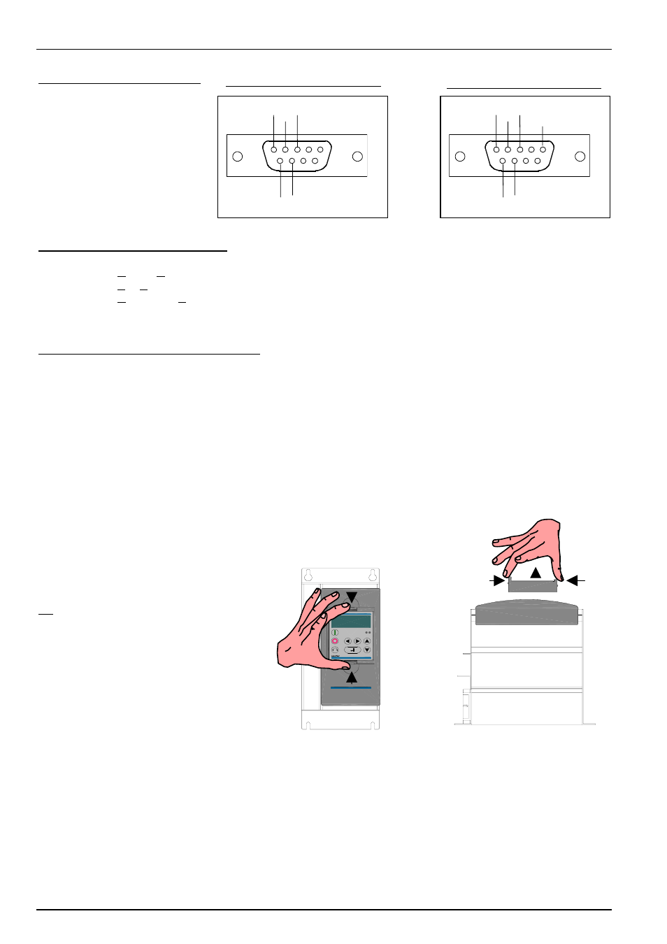
SUB-D connector assignment
InterBus status LEDs (see Chap. 5.3):
UL (green):
Supply voltage applied
RC (green):
RemoteCheck:
Remote bus to previous InterBus device OK
BA (green):
Bus Active:
InterBus data is
being exchanged (Bus running)
RD (yellow):
Remotebus Disabled: Remote bus to next InterBus device disabled
TR (green):
Transmit:
Data is being transferred from/to subscribers
Module status 2-colour LED (see Chap. 5.3):
ST (red):
Module error
ST (green):
Module status
2.1.2 Installation of technology units in the SK 700E
The technology units must be installed as follows:
1. Switch off the mains voltage, observe the waiting period.
2. Remove the dummy cover by actuating the unlocking device on the top and bottom edge.
3. Allow the technology unit to engage audibly by pressing lightly on the installation surface.
NOTE:
Installation of a technology box
separate to the frequency inverter is
not possible. It must be connected
directly to the inverter.
2.1.3 Installing the FE (PE) connection
A flat plug is provided on the outgoing IBS interface for connection to the FE (function earth) or PE. The
accompanying green-yellow cable must be mounted here and fastened to the housing of the frequency inverter.
GND
DI
6
1
5
9
DO
/DO /DI
GND
DI
6
1
5
9
DO
/DO
/DI
+5V_OUT
(100mA)
Incoming remote bus:
Forwarding remote bus:
7 0 0 E
N O R D A C
7 0 0 E
N O R D A C