7 example telegrams, 1 switch-on block → standby – NORD Drivesystems BU0070 User Manual
Page 32
NORDAC InterBus Operating Manual
32
Subject to technical alterations
BU 0070 GB
7 Example telegrams
Various example telegrams are shown below to clarify the control and parameterisation of the frequency inverter
with InterBus.
7.1 Switch-on block
→ Standby
A frequency inverter must be switched from the "Switch-on block" status (STW Bit 0 – 0), which is active when the
device is switched on, to the "Standby" status (STW Bit 0 = 1). Parameter set 1 is valid. Only the PZD channel is
evaluated.
Procedure:
• Check last status word (ZSW 0A 70)
• Generate control word (STW 04 7E)
• Check response telegram (ZSW 0A 31)
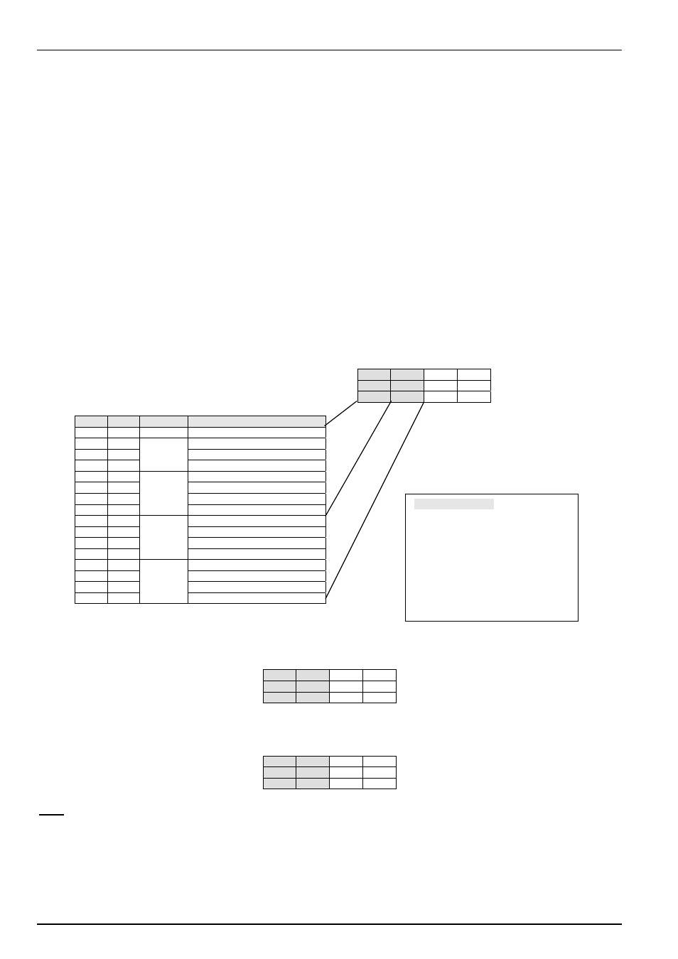
Details:
Status word of frequency inverter
→ frequency inverter is in switch-on block status
9
10
11 12
ZSW
ZSW
IW1
IW1
0B
70
00 00
Bit
Value
Value
HEX
Significance
15
0
0
Parameter set Bit 1 off
14
0
Parameter set Bit 0 off
13 0
Reserved
12
0
Rotation left is off
11 1
B
Rotation right is on
10 0
Reference
value
undershot
9 1
Bus
controller
8
1
Setpoint = actual value
7 0 7 No
warning
6 1
Switch-on
block
5
1
No emergency stop
4 1
Block
voltage
3 0 0 No
errors
2 0
Operation
blocked
1
0
Not ready for operation
0
0
Not at standby
To switch the frequency inverter to the Standby status, the following telegram must be sent:
9
10
11 12
STW
STW
SW1 SW1
04
7E
00 00
When the frequency inverter switches to the Standby status, it sends the following response telegram:
9
10
11 12
ZSW
ZSW
IW1 IW1
0B
31
00 00
Note:
The control telegram must be sent cyclically as the frequency inverter may not switch to the required
status within the response time of a telegram.
Abbreviations used:
PKW
Parameter identifier Value
PZD Process
data
PKE Parameter
identifier
IND Index
PWE Parameter
Value
STW Control
word
1
ZSW
Status word 1
SW1..3 Setpoint
IW1..3 Actual
value