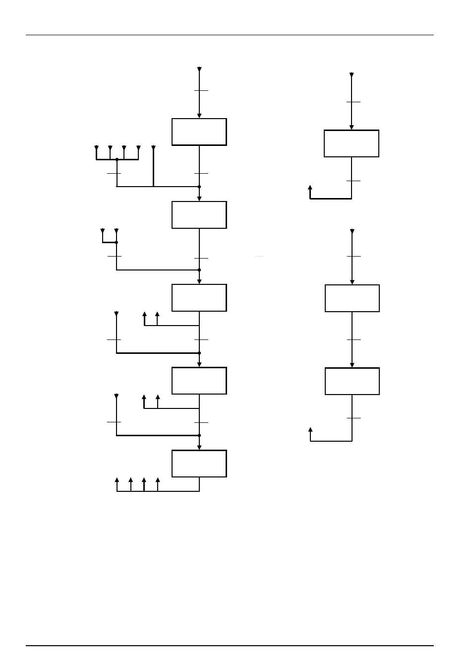
Internal status machine – NORD Drivesystems BU0070 User Manual
Page 28
NORDAC InterBus Operating Manual
28
Subject to technical alterations
BU 0070 GB
Sw itch-on block
Standby
activated
Operation
enabled
Emergency
stop active
Error reaction
active
Error
From every device status
3
4
5
6
8
4
5
5
Not on standby
Sw itching on the inverter
Loading relay applied
Error
Error reaction
ended
Bit0 = 0:
Shut dow n
& Bit1 = 1:
Enable voltage
& Bit2 = 1:
Enable pulses
(xxxx x1xx xxxx x110)
Bit 3 = 0:
Block operation
Bit0 = 1:
Sw itch on
Bit3 = 1:
Enable operation
Bit2 = 0:
Emergency stop
Bit1 = 0:
Block voltage
v Bit2 = 0:
Emergency stop
Priority of control com m ands:
1. Block voltage
2. Emergency stop
3. Shut dow n
4. Enable operation
5. Sw itch on
6. Block operation
7. Reset error
Designation of states:
1: Bit 0 = 0
2: Bit 6 = 1
3: Bit 0 = 1
4: Bit 1 = 1
5: Bit 2 = 1
6: Bit 5 = 0
7: Bit 2 & Bit 3 = 1
8: Bit 3 = 1
3
5
2
3
3
6
4
2
2
1
2
3
7
8
f = 0 reached
(Emergency stop ended)
Bit7 0
Î
1
error acknow ledgement
Control bits
0. Ready for operation / shut dow n
1. Block / enable voltage
2. Enable pulses / emergency stop
3. Block / enable operation
4. Operation condition / block RUE
5. Enable / stop RUE
6. Block / enable setpoint
7. Error acknow ledgement (0
Î
1)
10. Control data valid / invalid
11. Rotation right
12. Rotation left
14. Parameter set Bit 0
15. Parameter set Bit 1
4
5
6
Bit4 = 0:
Move dow n emergency ramp and
remain in "Operation enabled"
Bit5 = 0:
Hold frequency
Bit6 = 0:
Setpoint = 0%
Bit0 = 0:
Shut dow n
5
Bit3 = 1:
Enable operation
& Bit0 = 1
: Sw itch on
2
Internal status machine
2