NORD Drivesystems BU0070 User Manual
Page 12
NORDAC InterBus Operating Manual
12
Subject to technical alterations
BU 0070 GB
3 Bus configuration
An InterBus network consists of a maximum of 256 subscribers and is based on a ring topology. The number of
subscribers is dependent on the number of IO's. With a useful data length of 3 words, it is possible to connect 85
devices with the NORDAC 700E.
3.1 Laying the bus cables
In an industrial environment the correct installation of the Bus system is particularly important in order to reduce
potential interference. The following points are designed to help prevent interference and problems right from the
start. The installation guidelines are not complete as applicable safety and accident prevention guidelines must
also be complied with.
3.2 Cable material
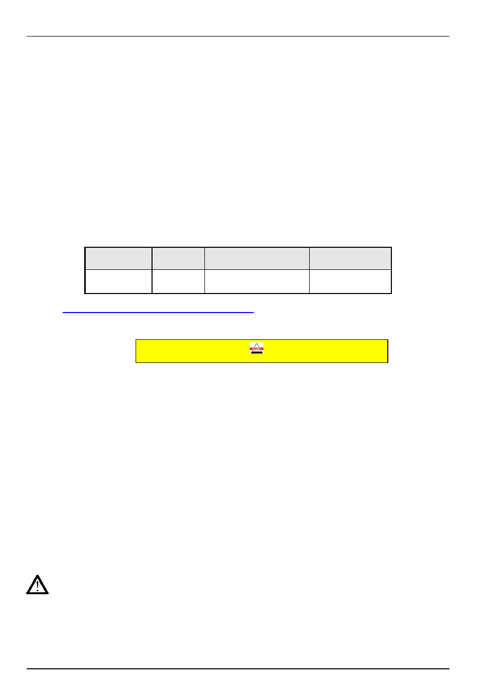
The guaranteed transfer speeds or transfer distances can only be achieved without errors if the specific cable
parameters are complied with.
Max. line
capacitance
Resistance
Cable cross-section
Baud rate
60nF/km
250m
Ω/m
3*2*0.2 mm
2
500k
See also
http://www.interbusclub.com/de/doku/pdf/kabel-d.pdf
Certified InterBus data cables are recommended.
Designation (example):
3.3 Cable layout and shielding (EMC measures)
If EMC measures are not in place, high-frequency interference which is principally brought about by switch
procedures or lightning often causes electronic components in the bus subscribers to be faulty and error-free
operation can no longer be ensured.
Appropriate shielding of the bus cable reduces electrical interference which can arise in an industrial environment.
You can achieve the best shielding qualities with the following measures
• Connect the bus subscribers with the shortest amount of cable possible.
• The shielding on the bus line must be applied completely on both sides.
• Avoid using tap lines to connect field devices to the bus.
• Avoid extending the bus lines using plug connectors.
Bus lines should be laid with a minimum spacing of 20 cm to other lines which carry a voltage higher than 60V.
This applies to lines laid inside and outside of control cabinets.
If earthing potential values are different, transient current may flow through shielding which is connected on
both sides. This may be a danger to electronic components. Differences in potential must be reduced using
sufficient potential equalisation.
INTERBUS
Certified! No. xxx