2 the status machine – NORD Drivesystems BU0070 User Manual
Page 27
6 Data transmission
BU 0070 GB
Subject to technical alterations
27
With the setting ‘Digital I/O status’, the states of the control terminals and the relay (MFR) can be transferred:
Bit
Status
Bit 0 -5
Digital input 1-6
Bit 6-11 for Posicon special extension unit Digital input 7-12
Bit 6 for encoder special extension unit
Digital input 7
Bit 12 -15
Multifunctional relay 1-4
With the settings ‘Actual position’ and ‘Setpoint position’, the actual absolute position is transferred. The resolution
is 1 = 0.001 revolutions. If the value ‘Setpoint position 32 Bit’ is set in parameter P546 ‘Setpoint 1 function’, the
actual value of the setpoint or actual position is also transferred as a 32 Bit value in PZD2 and PZD3:
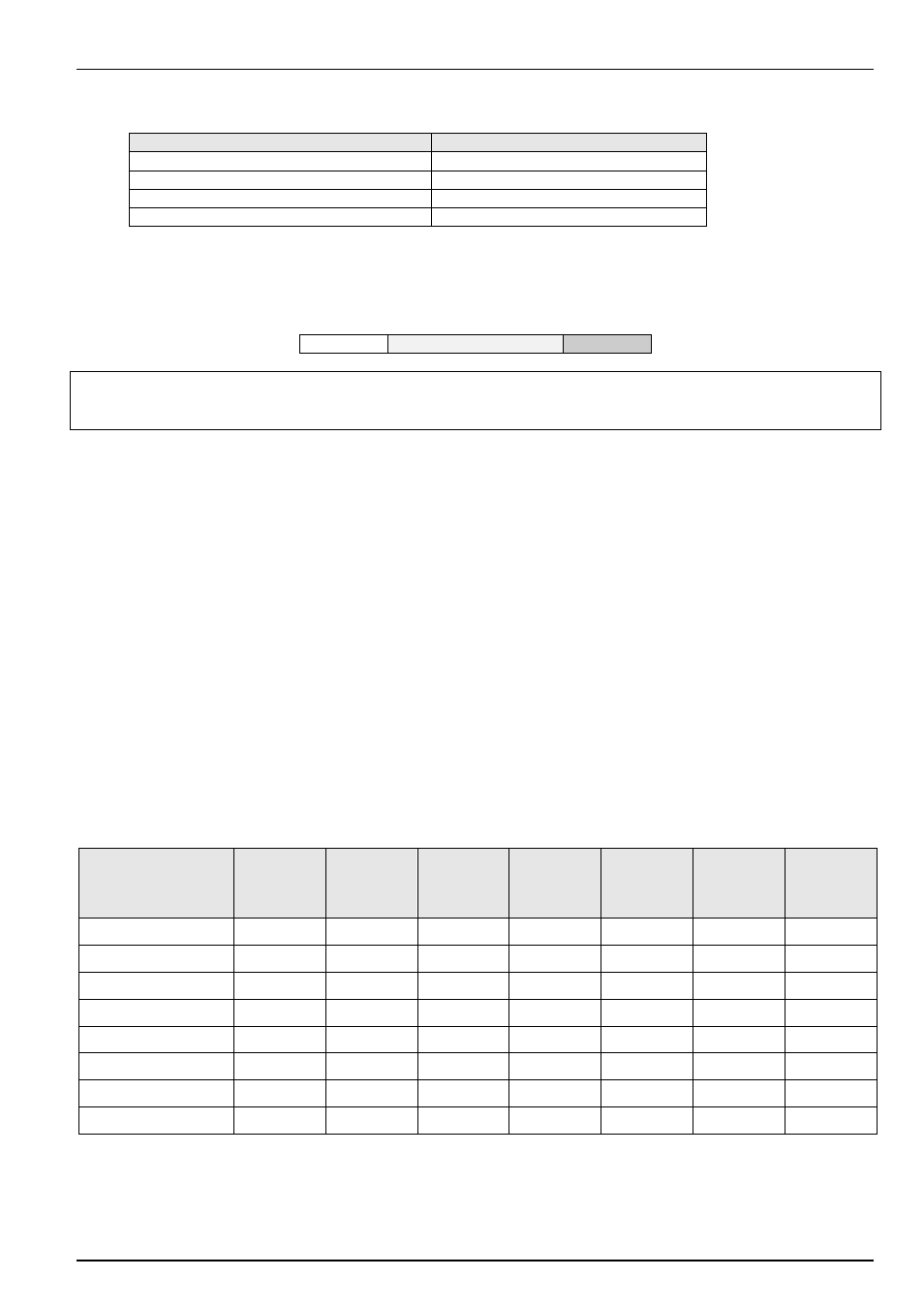
PZD1 PZD2 PZD3 PZD3
ZSW
IW1
IW2
Please notice: with all SK5XXE inverter units the SW2 and SW3 are exchanged and IW2 and IW3 are
exchanged, too. So the setpoints protocol is STW – SW1 – SW2 – SW3 and the status is ZSW – IW1 – IW2 –
IW3.
6.1.6 Actual value 2 and actual value 3 (IW2/3)
It is possible to forward two more actual values to the controller when PPO type 2 or 4 is used for transfer.
Actual value 2 (IW2) is transferred in PZD4. The value to be transferred can be selected in P544 (actual bus value
2). Actual value 3 (IW3) can be transmitted in PDZ3 if actual value 1 is not a 32 Bit value. The value to be
transferred can be selected in P545 (actual bus value 3). The standardisations correspond to those of actual value
1 (see above)
6.2 The status machine
The frequency inverter passes through a status machine. The changes between various states are triggered by the
respective control commands in the process data control word. The actual status is returned in the process data
status word.
After switching on, the inverter is in switch-on block status. This status can only be ended by transmitting the “Shut
down (Off 1)” command.
The answer to a master telegram normally does not yet contain a reaction to the control command. The controller
has to check the answers from the slaves as to whether the control command has been carried out.
The following Bits indicate the status of the frequency inverter:
Status
Bit6
Switch-on
block
Bit5
Emergency
stop
Bit 4
Block
voltage
Bit3
Error
Bit2
Operation
enabled
Bit1
Ready for
operation
Bit0
Standby
Not on standby
0
X
X
0
0
0
0
Switch-on
block 1 X X 0 0 0 0
Standby
0 1 1 0 0 0 1
activated
0 1 1 0 0 1 1
Operation
enabled 0 1 1 0 1 1 1
Error
0 X X 1 0 0 0
Error
active
0 X X 1 1 1 1
Emergency
stop
active
0 0 1 0 1 1 1