3 power and control terminal connection – NORD Drivesystems MI0700 User Manual
Page 61
3 Power and control terminal connection
MI 0700 GB-0414
61
SK 700E
Name
Function
[factory setting]
SK 5xxE
Customer unit
SK CU1-PBR
Part No.
Connector
Terminal No.
Name
Terminal strip
Terminal No.
Name
SK 5xxE
onboard
Part No.
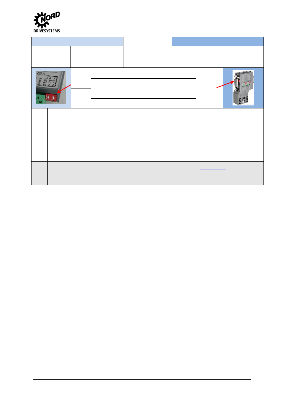
DIP left
PROFIBUS DP RTA
Sliding
switch
SUB-D9
ON = bottom
OFF = top
[Default = OFF]
activatable 120
Ω
terminal resistor
DIP
right
PROFIBUS DP RTB
*
Depending on the frequency inverter types and sizes, the supply voltages, terminal numbers or terminal names differ.
Terminal X5: 42 / VO 15V for SK 500E, SK 510E, SK 511E, SK 520E, SK 530E and SK 540E, all sizes 1 - 4
Terminal X5: 44 / VI 24V for SK 505E, SK 515E, SK 535E and SK 545E, all sizes 1 - 4, VI 24V is mandatory for 24 V supply
of the digital inputs and the control unit of the frequency inverter. This terminal is also available on terminal block X7, X12
and X15.
Terminal X5: 44 / VO 24V for SK 505E, SK 515E, SK 535E and SK
545E, ≥ size 5, VO 24V is available as 24 V output
voltage for supplying the digital inputs. This terminal is also available on terminal block X7.
For more information, refer to manuals BU 0500 or BU 0505 (se
**
For more information on the technology unit SK TU3-PBR, refer to manual BU 0020 (se
As an option, the technology unit SK TU3-PBR-24V (27590160) can be operated with an external 24 V power supply. Manual
BU 0020 provides more information.
Table 38: Field bus customer unit PROFIBUS DP, SK CU1-PBR