NORD Drivesystems BU0230 User Manual
Page 51
4 Parameterisation
BU 0230 GB-2712
51
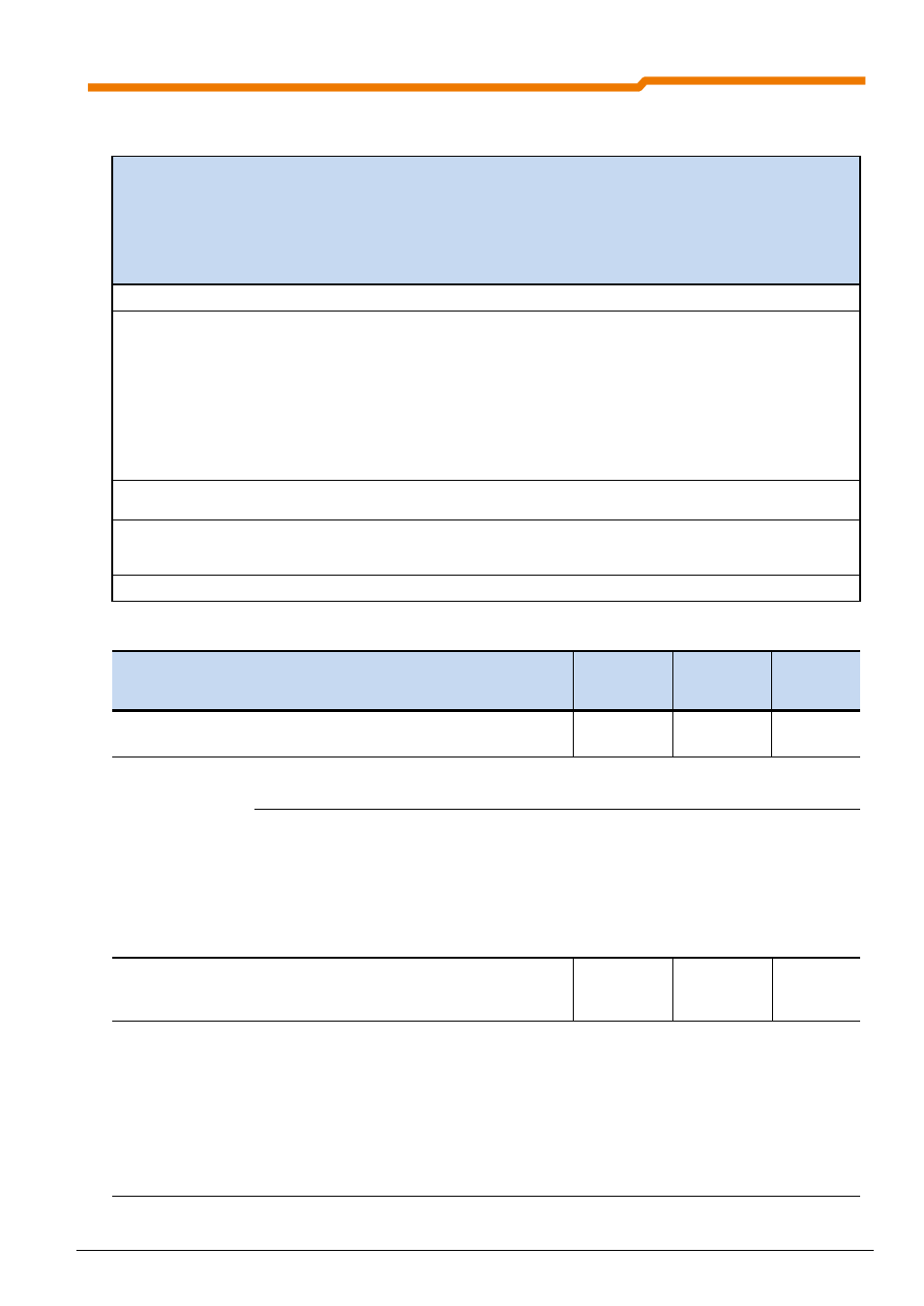
List of functions relevant to the functional safety of digital output P434
Value Function
Description
Output ...
with limiting
value or
function
(see
also
P435)
0
No function
Output switched off.
Low
1
External brake
To control an external 24V brake relay. The output switches at a
programmed absolute minimum frequency (P505).
For typical brakes a setpoint delay of 0.2-0.3 s should be
programmed (see also P107/P114).
A typical motor brake (105-180-205 V) can be connected directly via
the control terminals 79 MB+/80 MB-. (see also BU 0200)
Note:
Control of the brake is not fail-safe!
High
7
Fault
General fault message, fault is active or not yet acknowledged.
Fault - Low (Ready - High)
Low
33
Status of DIN4 or
"safe pulse block"
The status of digital Input 4 is depicted. For the devices SK 210E,
SK 215E, SK 230E and SK 235E this corresponds to the state of
"safe pulse block" on the input terminals.
High
39
STO inactive
This function depicts the reaction of the "safe pulse block".
High
Parameter
[factory setting]
Setting value / Description / Note
Device
Supervisor
Parameter
set
P435
[-01]
[-02]
Standardisation of digital output
-400 ... 400 %
[ 100 ]
[-01] = Digital output 1, Digital output 1 of the frequency inverter
[-02] = Digital output 2, Digital output 2 of the frequency inverter (only SK 2x0E)
Adjustment of the limiting values of the output function. For a negative value, the output function
will be output negative.
Reference to the following values:
Current limit (3) = x [%]
P203 >Rated motor current<
Torque current limit (4) = x [%]
P203
P206 (calculated rated motor torque)
Frequency limit (5) = x [%]
P201 >Rated motor frequency<
P475
… [-01]
...
... [-04]
Switch on/off delay
S
-30.000 ... 30,000 sec
[ 0.000 ]
Adjustable on/off delay for the digital inputs. Use as a switch-on filter or simple process control is
possible.
[-01] = Digital input 1
[-02] = Digital input 2
[-03] = Digital input 3
[-04] = Digital input 4
Positive values = switch-on delayed
Negative values = switch-off delayed
For the use of a digital output in the context of
functional safety, a value of 0 s must be set.
For process control, the formation of the delay time is
not fail-safe.