A) normal travel path b) optimised travel path – NORD Drivesystems BU0210 User Manual
Page 21
3 Function description
BU 0210 GB
Subject to technical amendments
21
3.2.4
Positioning
with absolute / incremental encoders in absolute mode
3.2.4.1
Optimised path positioning
with a single rotation of the encoder
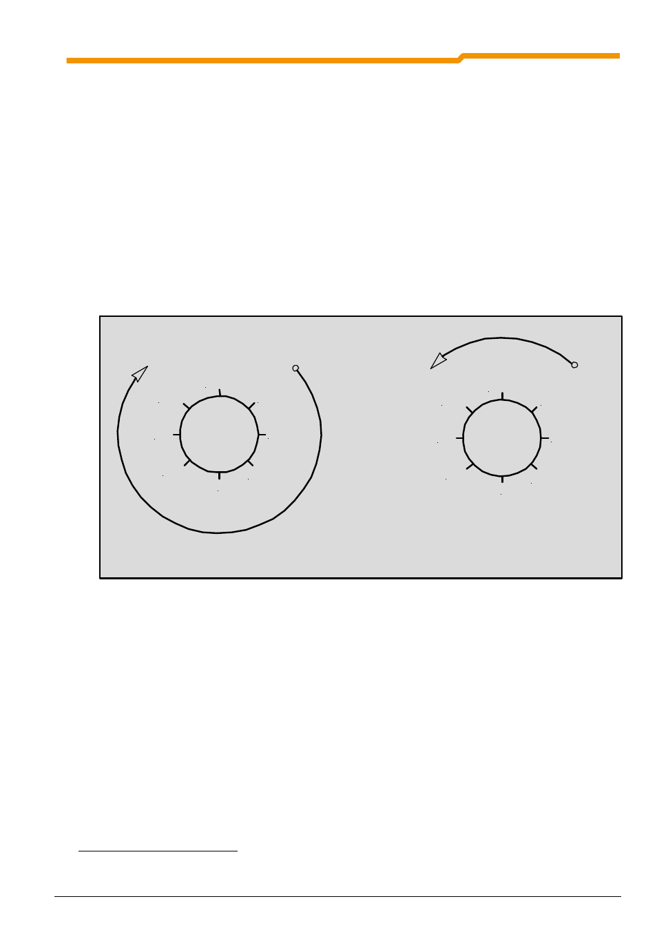
For rotating platforms in which the individual positions are divided around the circumference, there is the
problem that normally the optimal movement path from one position to the next must be set. However, with a
standard positioning, with a change of the setpoint position from -0.375 to + 0.375 the drive unit would select
the long movement path "around the outside" (See a).
The situation, or the longer movement path can be avoided if a CANopen absolute encoder in parameter
P604 "Encoder Type" with the settings 5 or 7 (CANopen absolute rotational encoder, optimised path) or an
incremental rotary encoder in the setting 3 (Incremental rotary encoder, absolute) or 4 (Incremental rotary
encoder, absolute with storage) is used. In this case, the short movement path is always selected. Here, the
drive unit passes over the overflow point
4
of the relevant rotary encoder (See b).
0.5 / -0.5
0
0.125
-0.125
0.25
-0.25
0.375
-0.375
0.5 / -0.5
0
0.125
-0.125
0.25
-0.25
0.375
-0.375
a) normal travel path
b) optimised travel path
The zero point of a single-turn absolute encoder is determined by where it is mounted and can be varied via
the parameter P609 [02] "Offset Position". If an incremental encoder is used, either a “Reference Point Run" or
a "Reset Position" function must be performed in order to determine the zero position. The zero position can
also be varied by means of an entry in parameter P609 [01] "Offset Position".
The above example is for a speed ratio or reduction ratio of "1". The maximum value of the position or the
overflow point is calculated as follows:
n
max
:
Maximum value of motor rotation
n
max
= 0.5 * Ü
b
/ U
n
Ü
b
:
Speed Ratio (P607[02])
U
n
:
Reduction Ratio (P608[02])
Example:
The absolute encoder or incremental encoder is installed on the output side of the gear unit.
The gear unit has a ratio of i=26.3.
n
max
=0.5 * 263 / 10= 13.15 rev.
4
The overflow point corresponds to 1/2 of a rotation of the encoder