Diagram & connectors – Hoyles CELLPHONE DETECTOR Plus 610 User Manual
Page 4
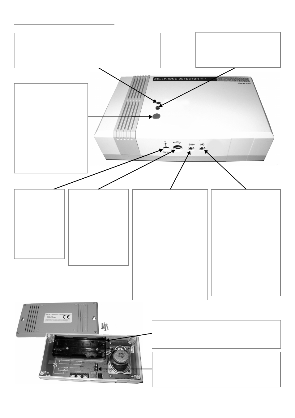
Diagram & Connectors
4
TEST / MUTE BUTTON
TEST Press the button
briefly to test the alarm.
MUTE Press the same
button briefly to silence
the alarm for 60 seconds
when it is sounding.
ON / OFF Press and hold
for 5 seconds to turn off
the detector, and repeat
to turn it back on.
ALARM OUT
This transmits a signal
to a remote monitoring
station. This output
could be wired to a
security office, nurse’s
station, control room, or
trigger an external
alarm system.
ALARM OUT is an
open collector NPN
transistor. On an alarm
it goes from high to low
(66Ω) impedance.
USB PORT
the Detector can be
connected to a PC
to be used with
Utilities Software.
When connected to
a PC via this port,
the unit does not
need batteries or DC
supply to operate.
AUDIO OUT
This connects to an
external amplifier or
powered speaker. The
AUDIO OUT can be used
to play the alarm directly
into a public address
system, extend the alarm
so that it can be heard
from several locations, or
amplify the audio. You can
use the utilities software to
disable the speaker and
only play the alert through
the Audio Out.
DC INPUT
Mains adaptors
are available as
an optional item.
Many
users
however prefer
the benefit of
wireless battery
installation.
BATTERY COMPARTMENT
To access the battery compartment locate the
four back cover screws and remove them.
TERMINAL BLOCKS
These are permanent discreet connection
alternatives to the external sockets located on
the base of the unit (see Specifications).
GREEN POWER LED
lights up solid when the unit is on and powered by
DC power adaptor. It will blink on every two seconds
when the unit is on and powered by batteries.
RED ALERT LED
can be switched off (by the
utilities software) if no visual
alarm is required.