Hoyles Six Zone Assistance Call Panel for Toilet or Pool Alarms User Manual
Hoyles electronic developments ltd, Wiring for pool alarm system, Wrp-b-11
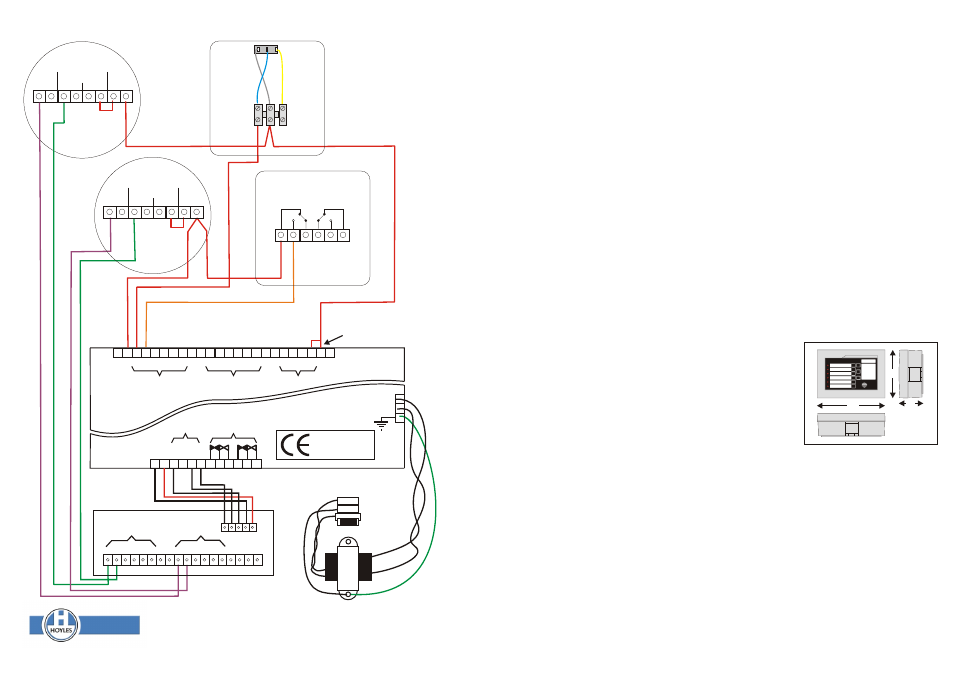
The system components for a toilet system The system components for a pool alarm system
AA31110D Controller
AA31110D Controller
S1600 Non-latching Pull Cords with LEDs or
WRP-B-11 Latching waterproof call points or
S1705P Non-latching Call buttons with LEDs
S1711WP Latching twist to reset call buttons
S1708PR Reset buttons or
8581750/HB Sounder beacon
S1708S Stainless Steel Reset Buttons
LAB35200 Call point signs
S1778PR Overdoor Light/buzzer or
S1778SR S/ Steel Overdoor Light/buzzer
Z1
Z2
Z3
Z4
Z5
Z6
F3
MULTIGUARD 2000 - 6
197
138
72
Dimensions (mm)
MULTIGUARD AIDALARM AA31110D
INSTALLATION INSTRUCTIONS
IT IS IMPORTANT TO FIX THE
Connection & Power Up se-
MULTIGUARD TO A FLAT quence.
S U R F A C E . I F T H E B O X The MULTIGUARD has a short
DISTORTS IT IS DIFFICULT TO
test or verification sequence on
C L I P T H E V A R I O U S power up. You should verify that
COMPONENTS TOGETHER
the unit as supplied is function-
T O F O R M A S E C U R E ing normally before making any
HOUSING.
connections.
Cables may enter through the
1. Ensure F4 is linked to +ve.
20mm holes in the rear of the
& Yellow) and earth lead (Green)
Plug in the battery. The plug is
box or through the entry slots lo-
are connected to the PCB.
polarised to maintain the correct
cated on each side. As the
polarity. The integral sounder
4. Reconnect the battery, the sys-
mains power cable is generally
will beep at 1 second intervals.
tem will once again go through
the largest it should be routed
Press the SILENCE button F1.
the test routine. Clip the PCB as-
into the central compartment
The LED's will flash three times
sembly onto the back box.
and dressed in for connection to
and then reset automatically.
4. Switch on the power at the
the fused terminal before dress-
Disconnect the battery.
fused spur. Observe the green
i n g i n t h e l o w v o l t a g e
2. Dress the cables into the ca-
Mains On LED.
cables.Low voltage cables
ble channel, trim to length and
6. The system can now be tested
should be routed into the cable
terminate as per the connection
and the decal marked up and lid
channel between the inner and
diagram. Any excess cable
clipped into place.The mark re-
outer walls of the box. These ca-
should be left in the side chan-
sistant decal covers a remov-
bles should only be cut to length
nels between the clip and the
able identification panel which
when you are ready to terminate
outer wall. This helps to prevent
can be created by a word pro-
them on the PCB assembly. Be
the clips deforming.
cessor or graphics package to
sure to leave enough length to al-
3. Connect the mains cable from
enable a professional looking fa-
low the PCB assembly to be re-
a suitable fused spur to the Live,
cia to be achieved for each in-
moved for access to the fuses
Neu tra l & E art h te rmi nal s. stallation. Two example blanks
and battery terminals at a later
Ensure the mains fuse is fitted
are supplied with these instruc-
stage.
and the transformer leads (Blue
tions.
Strobe Sounder Strobe
-ve -ve +ve +ve
8581750/HB
1 2 3 4 5 6 7 8 9
Zones 1-6 for
buzzer outputs
Strobe Sounder Strobe
-ve -ve +ve +ve
- + 1 2 3 4 5 6 + + 1 2 3 4 5 6 + + 1 2 3 4 + -
8581750/HB
INPUTS
- + X S D C
Zones 1-6 for
LED outputs
SERIAL
OUTPUT
10 11 12 13 14 15 16
-ve +ve
ZONE RESETS
RELAY
OUTPUT
B
lu
e
Wiring for Pool Alarm system
N
O
C
O
M
N
C
W
h
it
e
WRP-B-11
FUNCTION
INPUTS
Y
e
llo
w
S1711WP
AA31110D
Complies with Council
Directive 89/336/EEC
AA31110D
+ve 12vdc can be taken from
any +ve terminal on the pcb
they are all common
Mains Fuse
F4 must be linked to +ve
to use normally open
switch inputs
Dwg No:60060 Iss 4 November 2012
N
E
L
16vac
Input
T. 01744 886600 F. 01744 886607 E. [email protected] W. www.hoyles.com
Hoyles Electronic Developments Ltd
GENERAL
The AA31110D is designed to give audible and visual re-assurance indication at the point of operation.
Non latching (toilet alarm) and latching (pool alarm) devices can be used on the same controller. The
software deems that any alarm input for less than 5 seconds is a non latched input, therefore a disabled
toilet alarm signal and any alarm signal longer than 5 seconds is latched, therefore a pool alarm signal.
when latching buttons are used the MULTIGUARD will reset when the call point is reset. Separate reset
buttons are therefore not required for pool alarms.
OPERATION.
When a call point is operated the local indicators and buzzers operate to inform the caller that the call has
been transmitted. The zone LED at the panel also flashes and the integral buzzer sounds. The global alarm
relay switches while the buzzer sounds. When a call is silenced at the panel all flashing LEDs becomes
steady and all buzzers silence to inform everyone involved, that the call has been received and help is on
the way. When help finally arrives the call is reset at the point of activation. All LEDs and buzzers pertaining
to that zone will be extinguished and silenced. (If a toilet alarm input is seen by the panel after the zone has
been silenced, the zone will re-trip).
POWER SUPPLY
The AA31110D is supplied with an integral 13.8vdc power supply rated at 250ma with a rechargeable 0.7
Ahr standby battery. The MULTIGUARD has a power requirement of 25ma quiescent and 60ma maximum
with all zones tripped. The integral power supply will therefore support six zones plus the external ancilliary
equipment such as over door lights and buzzers. However, it will not support all zones tripped for long
periods. The standby battery will support the system for about six to eight hours in quiescent and
approximately 3 hours if two zones are tripped.
Note
X D C
gives steady output
to drive strobes