Hoyles GEMINI Battery powered fire alarm User Manual
Gx32 battery powered fire alarm system, Gx32cie, Hoyles electronic developments ltd
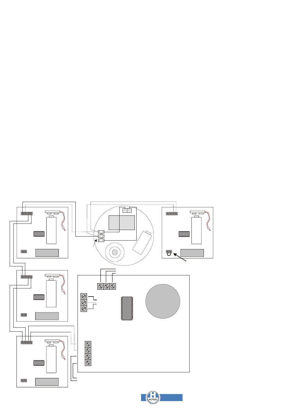
EOL
EA EB PA PB
EOL
EA EB PA PB
EOL
EA EB PA PB
EOL
EA EB PA PB
EB
EA
To Integral Callpoint
GX32CIE
GX32MCP
GX32MCP
GX32MCP
GX32MCP
PP3
PP3
PP3
PP3
Installation
Testing the system
It is assumed that installers are familiar with installing cables and fixing the
Turn the keyswitch to TEST MODE. The sounder will give a low pitch bleep
various components etc.. The system is battery powered and presents no
every 5 secs. Insert the black test key in the underside of the call point to
electrical risk to either installers or users. Callpoint/Sounder units are
displace the glass. Only the control sounder will sound. Remove the test key.
generally fitted at a height of 1.2m AFL. Remove the front cover and glass
While still in TEST MODE visit each call point in turn. Inserting the black test
and separate the back box. Pre-drill the back boxes if necessary to take the
key sounds only the sounder of the call point being tested. When all call
interconnection cable. Fit the back boxes to the wall and introduce the
points have been tested switch the control to the RESTART position.
cable. Strip the sheathing and cores as necessary.
Fault Finding
Start connecting at the remote End of Line unit and work back towards the
Fault indication is given audibly and visually at the control and
control panel. Connect the Amber and Blue of the cable to PA and PB
respectively. Fit a link in the terminals marked EOL. Connect the battery.
The unit should bleep. This will be repeated every 10 secs.. Re-assemble
the unit onto the back box. Refit the glass - the sounder will give a double
whoop within 10 secs. to confirm correct installation. Refit and secure the
front cover. If on fitting the glass and cover a long tone followed by double
bleeps every 5 secs. this indicates that there is a problem on the previous
section. This could be: a short or open circuit on the cable, a reverse
connection, no battery in the previous unit or no EOL link fitted.
At the next unit connect the Amber and Blue of the cable from the End of
Line unit to EA and EB respectively of this unit. Connect the Amber and
Blue of the cable leading towards the control panel to PA and PB
respectively. Reassemble the unit as above and check for the double
whoop on this unit.
Repeat the above procedure at each unit. Do NOT start to connect the next
call point until you have heard the double whoop confirmation. At the
control panel connect Amber and Blue to EA and EB respectively. Ensure
that the keyswitch is in the RESTART position. Connect the batteries
(observe the correct polarity). The green system healthy LED should start
to flash within 10 - 15 secs.. Fit the control panel front onto its back box. If
the green LED does not flash check the batteries and cable connections in
the control and the first call point.
can be caused
by exhausted or partially exhausted batteries, cable connections or cable
damage. If fault indication occurs on installation or on extending the system it
could be that the end of line link is not fitted or two have been fitted.
Switch to TEST MODE, any call point with a partially exhausted battery will
give a single high pitched bleep at 5 sec. intervals. Remove the callpoint and
replace the battery while in TEST MODE. All Callpoint and Control panel
batteries should be changed.
A double high pitched bleep every 5 secs. indicates that there is a cable fault
between the bleeping unit and the next unit towards the end of line. This
could also indicate a totally exhausted battery in the next unit.
Any battery replacements or cabling alterations should be done with the
keyswitch in TEST MODE otherwise it will be necessary to follow the
installation procedure above.
If only part of the system is sounding as a fire condition and it is not possible to
silence it from the control this would indicate that a cable has been damaged
and it is not possible for the silence signal to be received. In this case it will be
necessary to remove the batteries from the sounding call points and follow
the installation procedure above.
NOTE: The GX32CIE is not able to silence smoke alarms that are still
sensing smoke. If it is not possible to silence the call points beyond this
detector this would indicate that some of the batteries are approaching the
battery fail point. It will be necessary to clear the smoke first.
GX32 Battery Powered Fire Alarm System
Pre-wired do not alter
Pre-wired do not alter
Pre-wired
do not alter
Battery connections
Keyswitch
connections
E.O.L link must be fitted
to last call point on system
W:\Tech\Gemini GX32\Common\Installation Instructions\60074.cdr Page 1 Sep 2009 Iss 2
Amber
A
m
b
e
r
A
m
b
e
r
Amber
Amber
Blue
B
lu
e
B
lu
e
Blue
Blue
Black
Red
P
P
3
B
at
te
ry
- +
GX32SMi
GX32S/1
GX32 is available in kit form but
individual components can be
purchased as required.
GX32KIT400
1 x Gx32CIE Control Panel
4 x Gx32MCP Callpoint/sounders
GX32CAB140 140m twin cable
4 x CABCLIP5RBK 100 cable clips
GX32KIT402
1 x Gx32CIE Control Panel
4 x Gx32MCP Callpoint/sounders
2 x GX32SMi Ionisation smoke alarms
GX32CAB140 140m twin cable
4 x CABCLIP5RBK 100 cable clips
All kits and individual items are supplied
with batteries and fixing screws etc..
NOTE
Smoke alarms, where fitted, can
only be used between callpoint/
/sounder units. Only one can be
fitted between each as shown. Thus
32 smoke alarms would require 32
callpoint/sounder units.
Smoke alarms cannot be used at
the end of line.
Smoke alarms are provided with a
GX32S/1 termination unit to provide
the necessary termination
resistance for the GX32 system
www.hoyles.com
T. 01744 886600 E. [email protected]
F. 01744 886607 W. www.hoyles.com
Hoyles Electronic Developments Ltd