Hoyles Interguard 2 door Supervised Door Interlock System User Manual
Hoyles electronic developments ltd
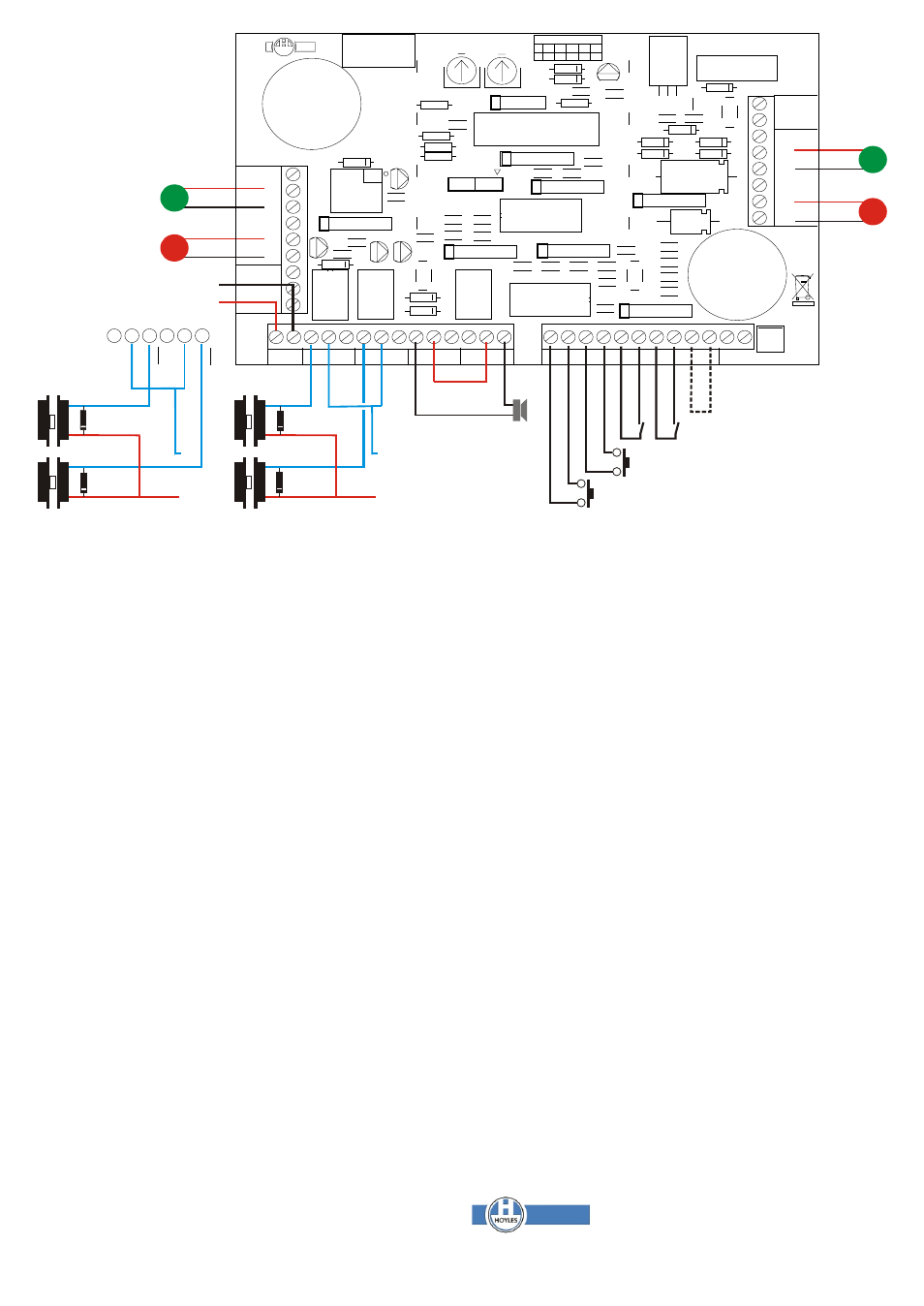
Remote Status
Indicators Door A
Remote
Status
Indicators
Door B
T1 = Dwell time 0-20 secs
T2 = DOTL time 20 - 60 secs
INTERGUARD IG222
Mode 2. Monitored device mode. (IN5 closed circuit)
The IG222 is a bi-directional two door interlock where the decision to
The IG222 powers up in the same way as above.
grant entry can be made by a supervisor to confirm identity via a vision
1. To pass through the airlock from say door A button A is pressed:-
panel or CCTV. The unit is powered by12/24vdc. The front panel
a. Lock A relay is energised to release door A.
incorporates pushbuttons for entry or egress and visual indication of door
b. The green LED for door A is illuminated.
status. Lock dwell time can be preset (0 - 20 secs). An integral buzzer
c. The red LED for door B is illuminated.
gives warning of Door Open Too Long (DOTL) adjustable from 20 - 60
2. Door A is then opened and the visitor passes into the airlock:-
secs., and breech conditions. A keyswitch with volt free DPCO contacts
a. Lock relay A remains energised for the dwell time to allow
is fitted to the front panel for user/engineer defined purposes.
door A to be used.(The visitor is now in the airlock. If the door A
is not closed then the DOTL timer commences. During this
An emergency door release unit should be fitted to allow egress
period the lock relay will follow presses of button A)
without resorting to supervisor control. This should be wired
3. When door A closes and locks:-
directly to the locking device.
a. The LEDs are extinguished.
Inputs.
4. Release button B is then pressed:-
inputs are provided for door/lock status contacts (IN3 & IN4), door
a. Lock B relay is energised to release (and open) door B
release buttons (IN1 & IN2) for unsupervised use. Secure devices such
b. The green LED for door B is illuminated
as fingerprint readers could be used.
c. The red LED for door A is illuminated.
Outputs
4. Door B is opened and the visitor to passes out of the airlock:-
Volt free SPCO relay contacts are provided for lock control (Lock A &
a. Lock relay B remains energised for the dwell time to allow
Lock B) and signalling breech conditions to remote locations. Outputs
door B to be used.
are also available for remote door status LEDs (L2,4,5 & 7)
5. When door B is closed and locked:-
Operation.
a. All LEDs are extinguished.
There are three modes of operation.
These procedures work in reverse to allow egress through door B.
Mode 1. Standard door strikes/mag locks and door contacts for door
status monitoring
Mode 3. Un-secured door mode. (IN1 and IN2 closed permanently)
Mode 2. Monitored door strikes/mag locks and/or automatic door
Both doors are fitted with locking devices and conventional door
openers/closers.
contacts. If any one door is opened the other is immediately locked and
Mode 3. Un-secured door mode for hands free un-supervised operation.
can only be opened when the first to open has closed. The second to
open then locks the first. This is used for hands free unsupervised
Mode 1. Standard mode. (IN5 open circuit)
operation eg. clean-rooms or temperature controlled areas. Well fitting
On power up the breech relay energises and no door LEDs are
locks, door contacts and closers are essential.
illuminated. Normally both doors are closed and locked to prevent entry
or egress.
DOTL
1. To pass through the airlock from say door A button A is pressed:-
If a door is released and opened but not re-closed within the DOTL period
a. Lock A relay is energised to release door A.
two red flashing LEDs and the relevant green LED give indication along
b. The green LED for door A is illuminated.
with an audible bleep. Normality is resumed when the door is closed. If
c. The red LED for door B is illuminated.
the door is not closed then the breech relay de-energises.
2. The visitor then passes into the airlock, closing door A:-
Breeched
a. Both LEDs are extinguished
If a door is forcibly opened both red LEDs will flash alternately with the
b. Lock relay A is de-energised to lock door A (The visitor is now
relevant green LED and audible warning will be given for about 90
in the airlock)
seconds. The breech relay will de-energise to signal to a remote point if
3. Release button B is then pressed:-
necessary. If the second door is then forcibly opened both green LEDs
a. Lock B relay is energised to release door B.
will flash alternately with the red LEDs.
b. The green LED for door B is illuminated.
c. The red LED for door B is extinguished.
4.The visitor passes through and door B is closed:-
a. All LEDs are extinguished.
b. Lock relay B is de-energised to lock door B.
BAT1
-
+
IC2
IC3
RLY3
RLY2
RLY1
PROGRAM
5
E
F
D
C
B
A
PRODUCT TYPE
6
4
3
2
1
www.hoyles.com
021-648 SPEB
PRODUCTION
CONTROL
LABEL
HED
BATTERY FUSE
T2
T1
MAX
MIN
+
+
+
+
TPR
+
+
+
+
+
NO
COM
NC
NO
NO
COM
COM
NC
NC
-
+
IN5
IN4
IN3
IN2
IN1
NO
NO
COM
COM
NC
NC
MM +
-
RELAY 3
RELAY 2
RELAY 2
RELAY 1
RELAY 1
C
D
S
L1
L2
L3
L4
L5
L6
L7
L8
TPR
12/24
vdc
IC1
1n4001
See note
1n4001
See note
Lock power: 12/24v dc or ac
depending on type of lock.
Note different connections for
different modes. For dc
devices fit a back emf diode
Remote Breech
Alarm if fitted
Door release buttons or
fingerprint readers if fitted
N.O close to release
A
A
B
B
Door or lock device contacts
Closed when door is locked
Mode change link
A
A
B
B
Connections
for modes 1 & 2
Connections
for modes 3
Dwg 60109 Issue 1 Jan 09
ve
+
T. 01744 886600 E. [email protected]
F. 01744 886607 W. www.hoyles.com
Hoyles Electronic Developments Ltd