Page 1, Specification, Interlocking principals – Hoyles Interguard 2/3/4 door control unit with steel case & 5A PSU User Manual
Page 3: Mode 1 without locks, Mode 1 with locks, Modes 2 and 3, Operational indications, Breach relay conditions, Fire alarm operations, Privacy and de-fog modes
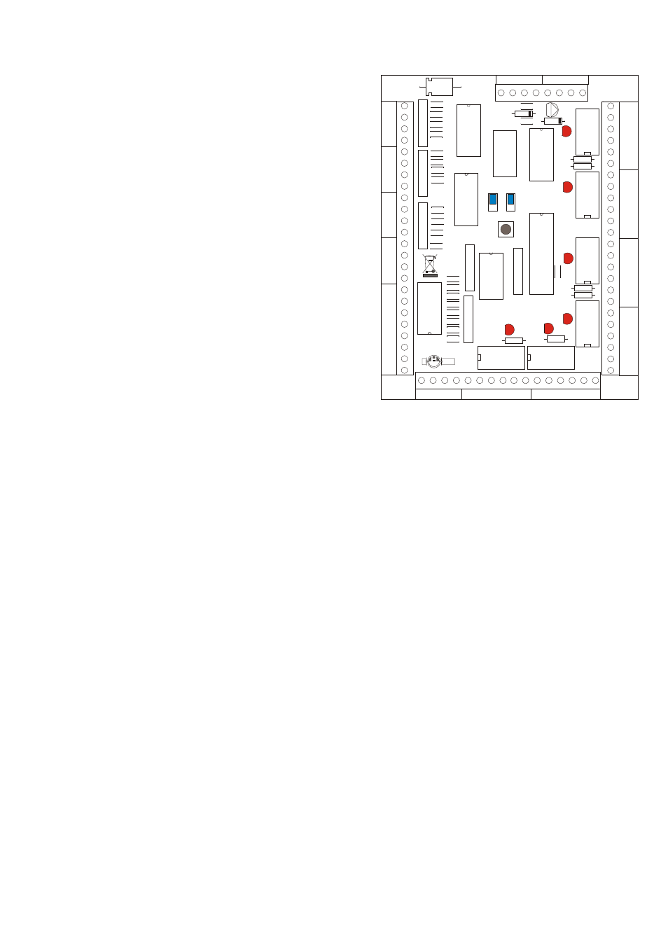
J1
J1
LED5
LED5
LED6
LED6
LED4
LED4
LED3
LED3
LED2
LED2
LED1
LED1
J2
J2
IC
2
IC
2
021-650SE ISSUE 1
021-650SE ISSUE 1
L
A
B
E
L
L
A
B
E
L
C
O
N
T
R
O
L
C
O
N
T
R
O
L
P
R
O
D
U
C
T
IO
N
P
R
O
D
U
C
T
IO
N
HED
HED
C
C
B
B
A
A
DC POWER
DC POWER
DC POWER
DC POWER
R
E
L
A
Y
1
R
E
L
A
Y
1
R
E
L
A
Y
2
R
E
L
A
Y
2
R
E
L
A
Y
3
R
E
L
A
Y
3
R
E
L
A
Y
4
R
E
L
A
Y
4
RELAY 6
RELAY 6
RELAY 5
RELAY 5
R
E
M
O
T
E
I
N
D
IC
A
T
IO
N
S
R
E
M
O
T
E
I
N
D
IC
A
T
IO
N
S
1
2
+
V
E
1
2
+
V
E
F
I
N
P
U
T
S
F
I
N
P
U
T
S
R
I
N
P
U
T
S
R
I
N
P
U
T
S
D
I
N
P
U
T
S
D
I
N
P
U
T
S
C
C
D
D
S
S
X
X
--
--
--
--
+
+
+
+
+
+
+
+
GN4
GN4
GN3
GN3
GN2
GN2
GN1
GN1
RD4
RD4
RD3
RD3
RD2
RD2
RD1
RD1
+
+
+
+
+
+
+
+
F4
F4
F3
F3
F2
F2
F1
F1
D4
D4
R4
R4
D3
D3
R3
R3
D2
D2
R2
R2
R1
R1
D1
D1
NC
NC
COM
COM
NO
NO
NC
NC
COM
COM
NO
NO
NC
NC
COM
COM
NO
NO
NC
NC
COM
COM
NO
NO
NC
NC
COM
COM
NO
NO
NC
NC
COM
COM
NO
NO
NC
NC
COM
COM
NO
NO
NO
NO
COM
COM
NC
NC
NC
NC
NO
NO
COM
COM
NC
NC
NO
NO
COM
COM
NC
NC
NO
NO
COM
COM
NO
NO
COM
COM
NC
NC
The IG432 Interlock controller is a configurable 2, 3 or 4 door interlock controller
also providing the user with good door / interlock status indication at the doors.
Specification
The unit requires 12v dc power, normally from the separate internal
power supply.
The 4 x D inputs are for 4 normally closed door contacts (closed
when the door is closed).
The 4 x R inputs are 4 normally open request to release inputs
(close to request).
The 4 x F inputs are 4 x normally open function inputs (close to
invoke the function).
The 4 +ve terminals are for the input references, e.g. R links to + to
request to release. D links to + to show that the door is closed and F
links to + to invoke the function. These are also the +ve feeds for the
remote (at the door) led indications.
The remote indications are switched -ve for rd (red) and gn (green)
indications at the doors.
Each of the 6 relays has 2 sets of clean changeover contacts rated
2Amp at 12vdc.
Relays 1,2,3 and 4 are for the 4 door locks.
Relay 5 is the main breach relay. (Breach 1)
Relay 6 is the secondary breach relay. (Breach 2)
SDC is a serial output for future development.
X is a privacy/defog input to lock down doors 3 and 4 when privacy
is required. +ve applied to invoke.
Interlocking Principals
Interlocking in its simplest form is for 2 doors and in theory only one door can be open at once. There are three ways of achieving
this:
Mode 1 without locks.
Just trust the staff to look at the indications and close the doors.
Mode 1 with locks.
Keep all doors closed but unlocked, and lock the other doors if a door is opened. In this method door
sensing is critical. If a door is ajar, it may not register as open on a magnetic reed door contact, but it may be too far open for a
magnetic lock to pull the door closed. Other methods of door sensing can be used but the cost rises and the expansion /
contraction of doors and frames can result in more than one door being open at the same time. (Interlock Breached).
Modes 2 and 3.
Keep all doors closed and locked and release the relevant door on request only if available to be released i.e.
all other doors are locked.
The IG432 can be used in modes 1, 2 or 3 above. However, mode 2 or 3 are recommended for least breaches.
For a standard 2, 3 or 4 door interlock set both jumpers in the ‘A’ position.
Operational indications -
Red/Green indicators are provided at each door. Normally there are no indications, or with the
alternative indication, the green indicates steadily when the door is available for use.
When a door is legitimately used, it will indicate a steady green, with the other doors indicating a steady red.
If the interlock is breached, all door indicators will flash red and the door that caused the breach will alternate with green.
If the doors are all released via the fire inputs, all door indicators will flash green.
Breach relay conditions
There are 2 breach relays, (Relay 5) Breach 1 (normally energized, ie will operate if power is lost) and (Relay 6) Breach 2
(normally de-energised). If a door is forced, left open too long or a request button pressed for too long a period then Breach 1
relay operates. If there is a fire alarm input both breach relays will operate.
Fire Alarm operations
Mode 1 F1 and F2 fire alarm all doors will remain unlocked even when other doors are open.
Modes 2 and 3 F1 fire alarm all doors release.
Modes 2 and 3 F2 fire alarm disables the interlocking ie. all doors remain locked but all request to release are accepted and
release the doors for the dwell time even if other doors are open.
Privacy and de-fog modes
Both modes lock down all doors normally, or just the 2 door interlock if set as below. The doors indicate steady red.
Momentarily apply +ve to X for privacy mode for max. 20 minutes then back to normal, or momentarily apply +ve again to exit.
Apply the +ve to X for longer than 5 seconds for de-fog. The doors lock down until the signal is removed (no time limit).
3 door 2 door interlocks with a common door
Set both jumpers to the ‘B’ position for doors 1, 2 and 3 as a 3 door interlock and doors 3 and 4 as a 2 door interlock. This only
operates in mode 2 or mode 3. Ie. Request to Release are required.
Breach 1
Breach 2
Page 1