51 calibration 5.4, Calibration flow chart – West Control Solutions MRC 7000 Profiler Manual User Manual
Page 51
51
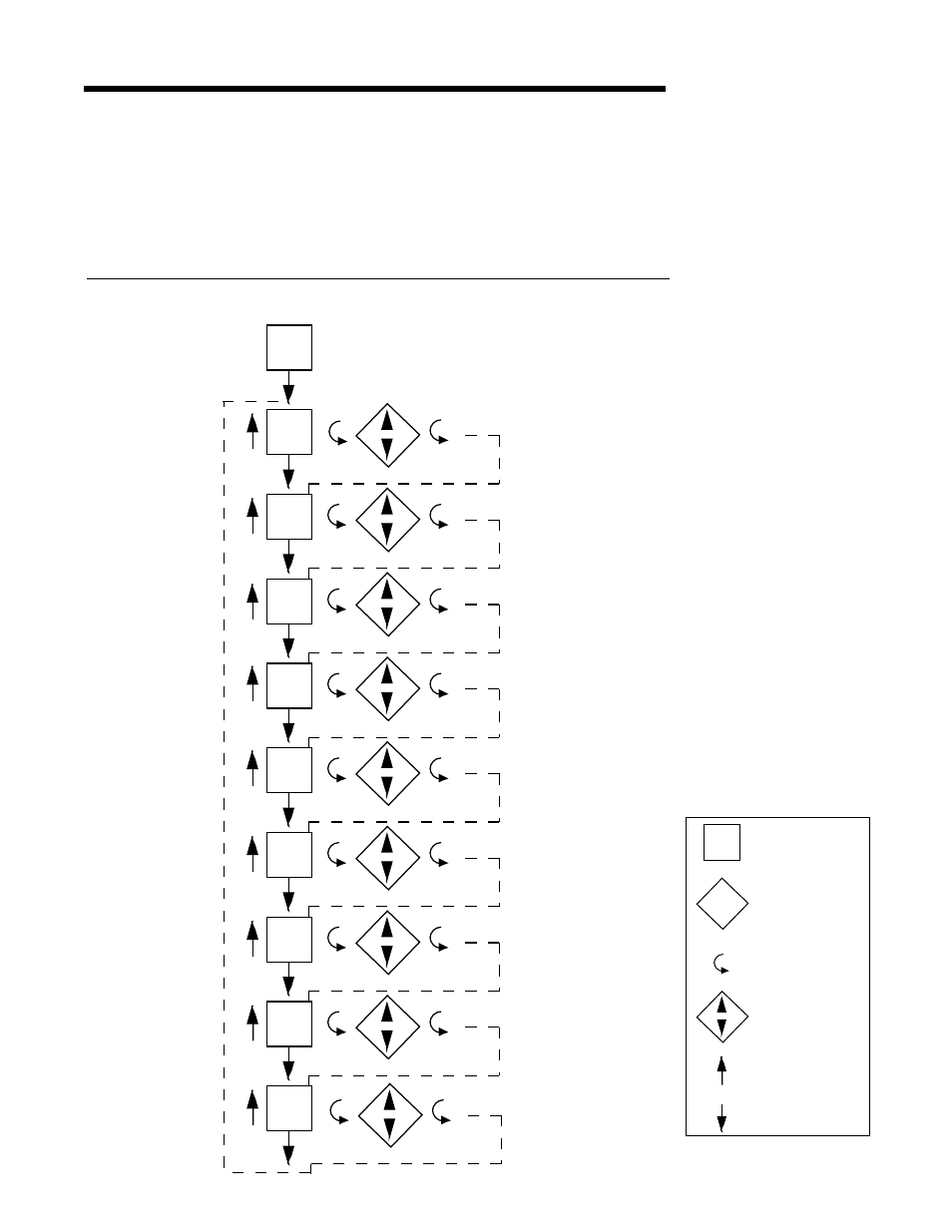
Calibration 5.4
CAUTION: Do not attempt any calibrations without the proper test equipment that meets or
exceeds the specifications listed.
Press and release the SCROLL key until CAL appears on the display , then press the DOWN
key to enter the mode. The display will change to CAL1. Press the SCROLL key to advance
the display to the other calibration modes available. For two pen units, CAL2 and CAL3 will
only need to be required on TB4 to calibrate Pen 1 and Pen 2 inputs. Both TB 4 and TB 5
inputs must be calibrated for thermocouple inputs. Table 5-1, page 52, provides a listing of
field calibration routines. All instruments are calibrated prior to shipment from factory.
CALIBRATION FLOW CHART
ON
OFF
Actual Display
On/Off Display -
Use arrow keys
to turn on or off
Scroll Key
Numeric Display -
Use arrow keys
to change value
Up Arrow Key
Down Arrow
KEY
CAL2
CAL3
CAL4
CAL5
CAL6
CAL1
CAL
CAL7
CAL8
CAL9
- 2300 (18 pages)
- 3300 (2 pages)
- 4100+ (177 pages)
- N4100 (79 pages)
- N4400 (38 pages)
- N6500 (2 pages)
- N6600 (114 pages)
- N8800 (88 pages)
- N8840 (90 pages)
- 9300 (2 pages)
- 9500 (24 pages)
- D280-1 (49 pages)
- KS 40-1 (60 pages)
- KS 40-1 Burner (40 pages)
- KS 45 (76 pages)
- KS 50-1 (72 pages)
- KS 90-1 (84 pages)
- KS 90-1 Programmer manual (84 pages)
- KS 94 (44 pages)
- ProVU 4 (184 pages)
- Pro-16 (88 pages)
- Pro-8 (72 pages)
- Pro-4 (84 pages)
- ProEC44 (274 pages)
- CI 45 (60 pages)
- SG 45 (56 pages)
- DataVU 5 (136 pages)
- DataVU 7 (208 pages)
- MRC 5000 Controller Manual (32 pages)
- MRC 5000 Recorder Manual (32 pages)
- MRC 7000 Controller Manual (74 pages)
- MRC 7000 Recorder Manual (64 pages)
- MRC 8000 (76 pages)
- MRC 9000 (318 pages)
- N8080 (for 1xxx) (40 pages)
- N8080 (for 2xxx) (39 pages)
- TB 40-1 Temperature Limiter (32 pages)
- TB 40-1 Temperature Monitor (32 pages)
- TB 45 Temperature Limiter (51 pages)
- TB 45 Temperature Monitor (52 pages)
- CALogix (44 pages)
- KS 800 Operating Instructions (36 pages)
- KS 800 ISO1745 Interface Manual (34 pages)
- KS 800 Profibus Interface Manual (52 pages)