West Control Solutions MRC 7000 Profiler Manual User Manual
Page 17
17
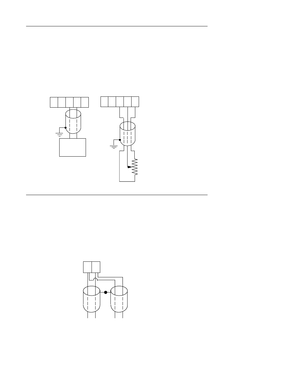
FIGURE 2-10
Remote Setpoint Input VDC, mADC (optional for the second pen of a dual pen instrument)
If Remote Setpoint option has been specified, make connections as shown. The remote
setpoint input may be selected as either 0 to 5 VDC or 1 to 5 VDC input in the Program mode
section. Make sure the configuration properly matches the input used. Connect the positive
lead to terminal 4, and the negative lead to terminal 3 (Terminal 3 is the ground, terminal 4 is
the input, terminal 5 is 5 VDC.) If a 4 to 20 mADC remote setpoint is to be used, the instru-
ment remote setpoint input should be configured for 1 to 5VDC in the Program mode, and a
250 ohm resistor should be installed across terminals 4 and 3.
FIGURE 2-11
Digital Communications Options
Connections are made as shown using TB2. Refer to the Protocol Manual, Form #2878 for
more details regarding the connections and how to use this option. This document is provided
only when this option has been specified. If the communications network continues on to other
instruments, connect the cable shields together, but not to the instrument. A terminating
resistor should be installed at the terminals of the last unit in the communications loop. If the
communications network ends at the instrument, the shield is not connected.
TOWARD THE
COMPUTER
TB2
1 2
NETWORK
CONTINUATION
(IF APPLICABLE)
Serial A
Serial B
1 2
3 4
5
+
-
TB4 or TB5
SHIELDED
TWISTED
PAIR
SOURCE
- +
1 2
3 4
5
+
-
TB4 or TB5
SHIELDED
MULTI-CONDUCTOR
CABLE
150 OHM
TO 10K OHM
POTENTIOMETER