Di2/3, 2-wire transmitter supply 8, Out3 as logic output 8, Out3 transmitter supply 8 – West Control Solutions KS 42-1 User Manual
Page 8: Electrical connections, If u, 6 out3 transmitter supply, 7 8 di2/3, u, Wire transmitter supply, Logic, 4v 12v
a
If U
T
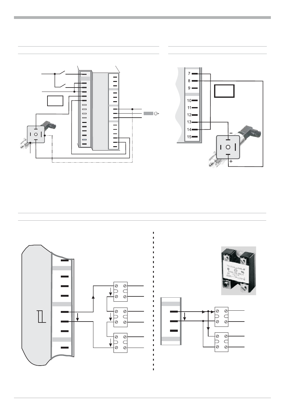
and the universal output OUT3 is used there may be no external galvanic
connection between measuring and output circuits!
Electrical connections
Terminal connection
8
Operating KS4x-1
1
2
3
K
+
-
+
-
13V
22mA
6 OUT3 transmitter supply
7
8
9
7
8
9
3
4
7
5
8
6
9
10
+
_
SSR
+
_
SSR
+
_
SSR
Series connection
Parallel connection
+
_
SSR
+
_
SSR
7
8
9
Logic
4V
4V
4V
12V
I
=22mA
max
I
=22mA
max
12V
6 OUT3 as logic output with solid-state relay (series and parallel connection)
Option
1
3
4
5
6
7
8
9
10
11
12
13
14
15
17
(2)
(16)
1
2
3
4
7
5
8
6
9
10
11
12
13
14
15
+24VDC
5mA
5mA
0V
1
2
3
K
+
-
+
-
+
-
17,5V
22mA
OUT3
J
x
7 8 di2/3, U
T
2-wire transmitter supply