KROHNE ALTOFLUX 2W IFM 4042K EN User Manual
Page 11
Part A Installation and Start-up
Section 2.1
02/2001
ALTOFLUX 2W
11
(OHFWULFDOFRQQHFWLRQ
2.1
Information on electrical connection and connection data
• Rated values: The flowmeter housings protect the electronic equipment from dust and
moisture and should always be kept properly closed. Creepage distances and clearances in air
have been dimensioned in conformity with VDE 0110 and IEC 664 for contamination category
2. Supply circuits and output circuits are designed to meet the standards of overvoltage classes
III and II, respectively.
• Safety isolation: The flowmeter must be provided with an isolating facility.
• Note information on instrument nameplate(s).
• PE conductor / FE functional ground must be connected to the separate U-clamp
terminal in the terminal compartment of the signal converter.
• For measurement reasons, the flowmeter must be properly grounded. The ground conductor
should not transmit any interference voltages. Therefore, do not ground any other electrical
devices together with this conductor.
• In hazardous areas, the ground conductor is used simultaneously for equipotential bonding.
CAUTION:
Where a power booster (1L= / 0L=) is used, electrical isolation is required
between the power booster and the current output, otherwise the electronic equipment will
substain irreparable damage.
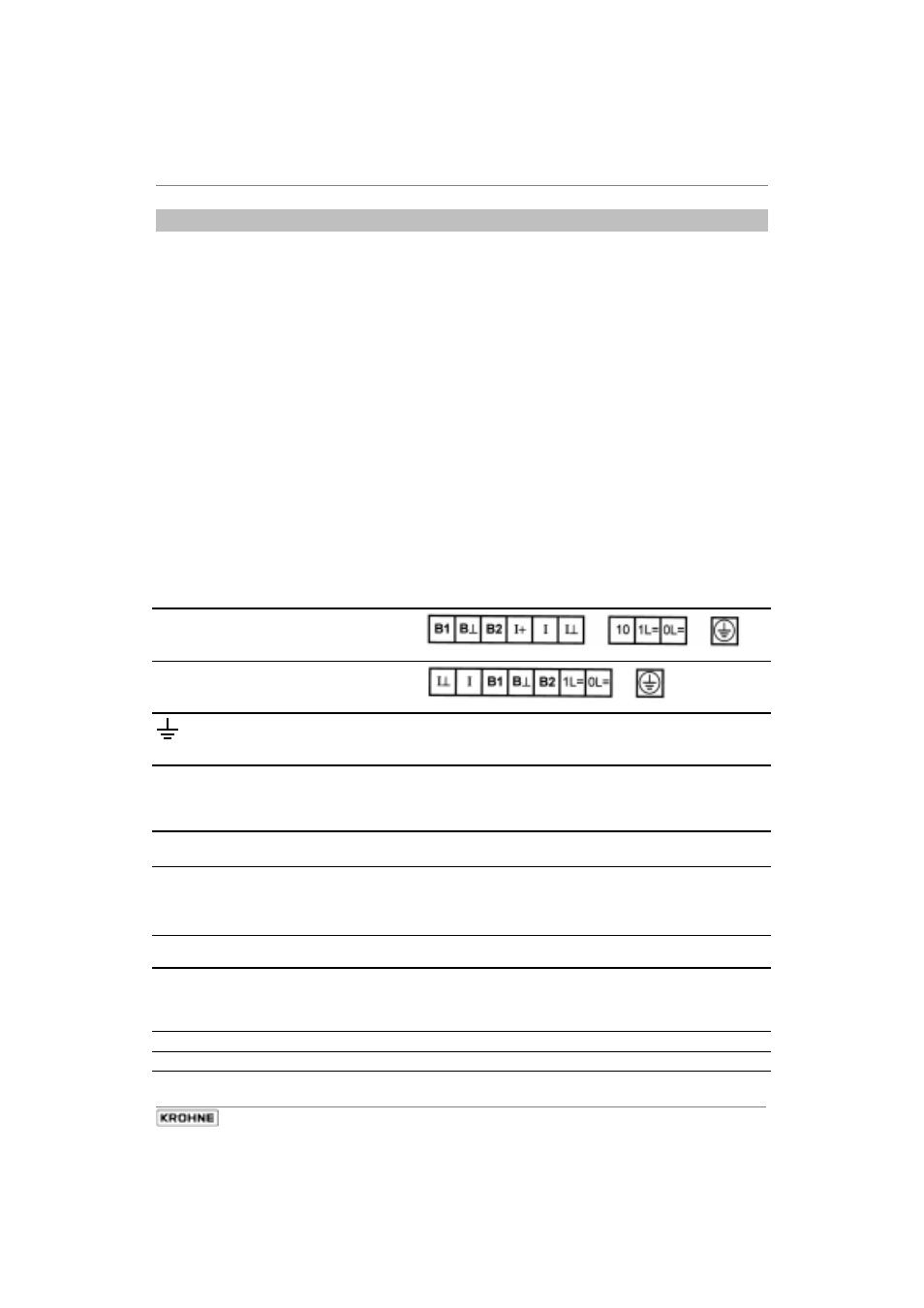
Standard power terminals
EEx power terminals
FE
PE
Functional ground
Safety conductor / equipotential bonding
Ι
Ι ⊥
Current output
(not polarity sensitive)
V
max
= 36 V
Ι
max
= 22.4 mA (fault current)
V
nom
= 24 V
Ι
nom
= 4 - 20 mA
V
min
= 14 V
Ι
min
= 3.6 mA (fault current)
B 2
B
⊥
Pulse or status output
NAMUR
NAMUR terminals (B2 + B
⊥)
Ι
open
= 0.4 mA
Ι
closed
= 6 mA
B 1
B
⊥
Pulse or status output
high current
High-current terminals (B1 + B
⊥)
closed:
V
max
= 2 V
Ι
max
= 100 mA
open:
V
max
= 36 V
Ι
max
= 2 mA
V
nom
= 24 V
Ι
nom
= 1,5 mA
B
⊥
Common ground (negative)
Take note of polarity!
1L=
0L=
Power booster
(not polarity sensitive)
2nd power terminal
V
max
= 36 V
V
min
= 14 V
V
nom
= 24 V
Ι
nom
= 22 mA
Ι
+
not used, no internal connection
10
for internal use only