Technical data, 4 antenna selection – KROHNE BM 702 A EN User Manual
Page 54
8
TECHNICAL DATA
54
BM 702 A
www.krohne.com
09/2009 - 4000643301 - MA BM 702 A R01 en
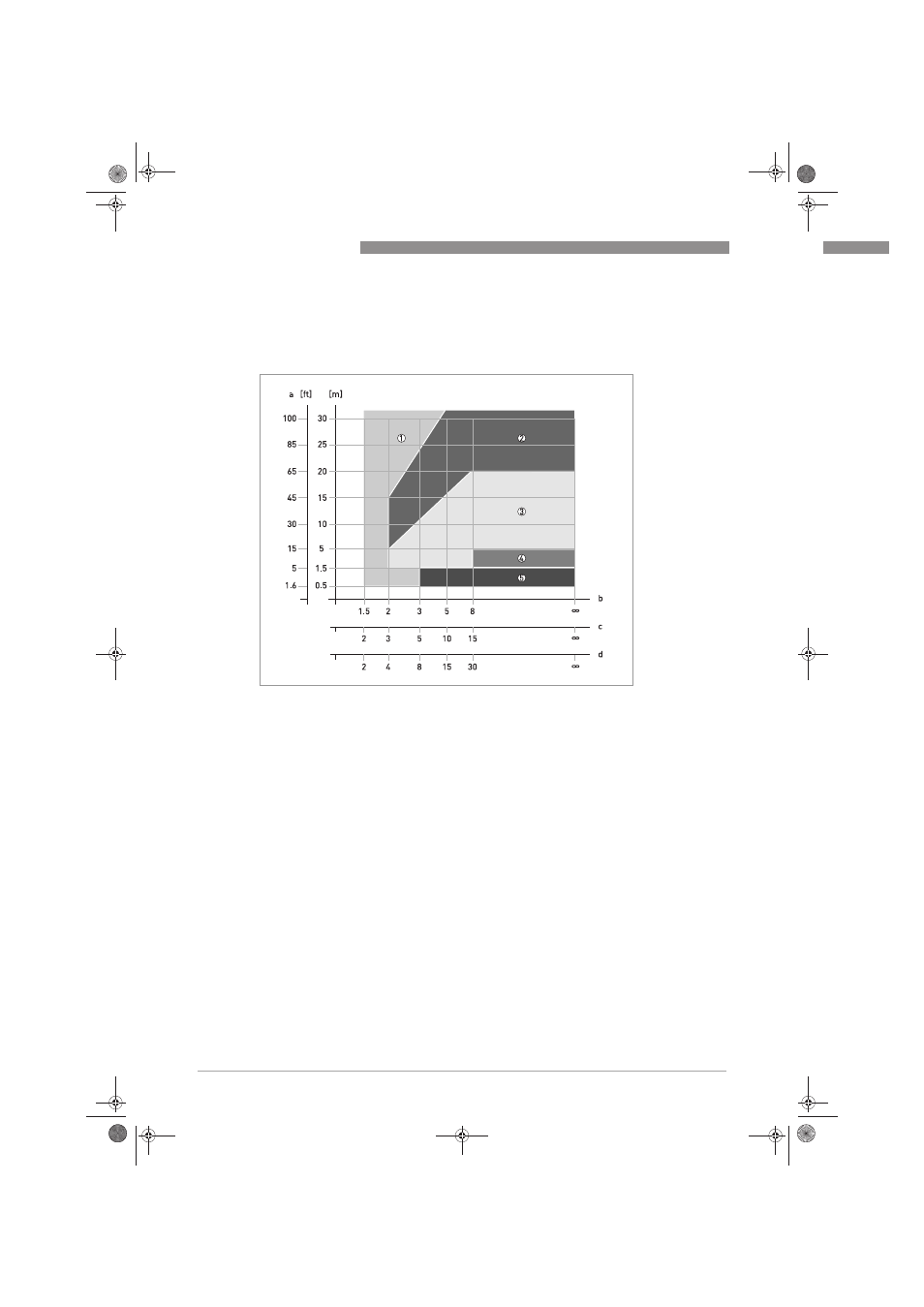
8.4 Antenna selection
The graph below shows which antenna to select for the application.
Graph of tank height / measuring range against dielectric constant ε
r
Figure 8-2: Selection of antenna
a = tank height / measuring range [ft / m]
b = ε
r
for storage tanks with smooth product surface
c = ε
r
for process tanks or foam
d = ε
r
for agitator tanks with vortex
1 Stilling well* (not for agitator tanks)
2 Stilling well* (not for agitator tanks) or antenna type 4
3 Stilling well* (not for agitator tanks); Wave-Stick or antenna type 3 and type 4
4 Stilling well* (not for agitator tanks); antenna type 2, type 3 and type 4 or Wave-Stick
5 Stilling well* (not for agitator tanks) or Wave-Stick
* Stilling well is equal to Wave-Guide antenna and bypass chamber
.book Page 54 Thursday, September 3, 2009 2:53 PM
- BATCHFLUX 5500 C Quickstart EN (20 pages)
- IFC 050 Converter Quickstart EN (28 pages)
- IFC 100 Converter Quickstart EN (32 pages)
- IFC 300 Converter Quickstart EN (68 pages)
- OPTIFLUX 1000 Quickstart EN (20 pages)
- OPTIFLUX 2000 Quickstart EN (24 pages)
- OPTIFLUX 4000 Quickstart EN (24 pages)
- OPTIFLUX 4040C Quickstart EN (16 pages)
- OPTIFLUX 5000 Flange Quickstart EN (20 pages)
- OPTIFLUX 5000 Sandwich Quickstart EN (20 pages)
- OPTIFLUX 6000 Quickstart EN (28 pages)
- OPTIFLUX 7300 Quickstart EN (24 pages)
- OPTIPROBE Quickstart EN (16 pages)
- TIDALFLUX 2300 F EN (44 pages)
- TIDALFLUX 2300 F Quickstart EN (24 pages)
- WATERFLUX 3000 EN (40 pages)
- WATERFLUX 3000 Quickstart EN (24 pages)
- WATERFLUX 3070 EN (80 pages)
- WATERFLUX 3070 Quickstart EN (32 pages)
- USB ADAPTER PLUS EMF EN (16 pages)
- IFC 050 Converter Modbus EN (20 pages)
- IFC 100 Converter FOUNDATION FIELDBUS EN (64 pages)
- IFC 100 Converter Modbus EN (20 pages)
- IFC 300 Converter FOUNDATION FIELDBUS EN (60 pages)
- IFC 300 Converter HART 0102 EN (20 pages)
- IFC 300 Converter HART 0201 EN (23 pages)
- IFC 300 Converter Modbus EN (24 pages)
- IFC 300 Converter PROFIBUS PA DP EN (40 pages)
- OPTIFLUX 2000-4000 IECEx EN (16 pages)
- OPTIFLUX 2000-4000-5000-6000-7300-IFC 300 Ex EN (40 pages)
- OPTIFLUX 2000-4000-5000-6000 -IFC 100 Ex EN (24 pages)
- OPTIFLUX 4040 C Ex EN (20 pages)
- OPTIFLUX x300 Ex Zone2 EN (1 page)
- H250 M9 ES EN (36 pages)
- VA 40-VA 45 EN (36 pages)
- H250 M10 ATEX II2G Ex d EN (16 pages)
- H250 M10 ATEX II3D Ex t EN (16 pages)
- H250 M40 ATEX II2D Ex t-II2G Ex d EN (20 pages)
- H250 M40 ATEX II2G Ex i EN (20 pages)
- H250 M40 ATEX II3G Ex nA EN (20 pages)
- H250 M40 Ex II2G Reed EN (2 pages)
- H250 M9 ATEX II2G Ex i EN (16 pages)
- H250 M9S ATEX II3D Ex t-II3G Ex nA EN (20 pages)
- M8E Converter HART 0101 EN (13 pages)
- DK 32-DK 34 ATEX II2G Ex i EN (16 pages)