Installation – KROHNE OPTITEMP TRA-TCA Plus EN User Manual
Page 34
3
INSTALLATION
34
OPTITEMP TRA/TCA PLUS
www.krohne.com
01/2012 - 4000630301 - MA OPTITEMP TRA/TCA Plus R01
3.6 Installation notes on the individual device classes
3.6.1 Weld-in thermometer
Compared to other types of fastening, welding in thermometers allows for higher process
pressures and flow velocities. Weld-in thermometers can be installed in two different ways:
• Welded in directly: possible in pipes and tanks with a wall thickness ≥20 mm / 0.79"
• Welded in using a welded sleeve: pipes and tanks with a wall thickness < 20 mm / 0.79"
require welding of a sleeve, into which the thermowell is then welded.
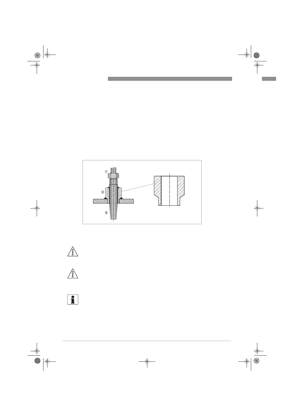
The following drawing shows a weld-in sleeve suitable for the TRA/TCA-T30 version:
Figure 3-6: Welded sleeve for thermometer thermowells according to DIN 43772, Form 4
1 Neck tube
2 Welded sleeve
3 Thermowell
CAUTION!
When installing welded sleeves, always make sure that the transition point between the conical
and straight part of the thermowell is flush with the inner wall of the pipe or tank. You, the user,
are responsible for proper welding, not the manufacturer!
CAUTION!
Sometimes even a neck tube cannot prevent the maximum permissible temperature in the
connection head from being exceeded! It does cause extensive thermal decoupling of the
connection head but you still have to always take into consideration the installation situation as
well as the ambient and process temperatures!
INFORMATION!
For more information on the dimensions of the welded sleeve, please see the
subsection "Dimensions" in the section "Technical Data". Note that the welded sleeve is not
included in the scope of standard delivery but is an optional accessory.
.backup.book Page 34 Tuesday, January 10, 2012 11:57 AM