13 master/slave configurations, 14 operator maintenance, Master/slave configurations -22 – KEPCO EL Series Electronic Load Operator Manual P/N 243-1295 Firmware Version 1.232 (Unit Rev 0 or 1) User Manual
Page 56: Operator maintenance -22, Analog programming control voltage scale -22, 13 for
3-22
SERIES EL 063010
3.13
MASTER/SLAVE CONFIGURATIONS
Up to 15 Series EL Electronic Loads may be paralleled for additional current handling capability.
All units must have the same voltage rating. One load is designated as the Master, and the rest
are designated as slaves. Refer to PAR. 2.6.3 for connections.
After the connections are complete, it is necessary to first turn on power to the slave(s), then
turn on power to the master, so that the master will recognize that slave(s) are connected. If
more than one slave is connected, power up the last slave in the chain first, then next to last,
etc. until all slaves are powered up, then turn on the master.
A Master/Slave combination responds to an *IDN? query with the *IDN string from first the Mas-
ter and then the Slave(s).
3.14
OPERATOR MAINTENANCE
No scheduled maintenance is required, other than to keep the high current connections tight
and to ensure all airways are clear of obstructions that could cause the load to overheat during
operation at higher power. Calibration Verification should be performed yearly or as required.
The exterior of the load should be cleaned periodically, as is necessary, using a soft cloth damp-
ened with a mild, non-abrasive, water-soluble detergent, and then rinsed with a water-damp-
ened soft cloth.
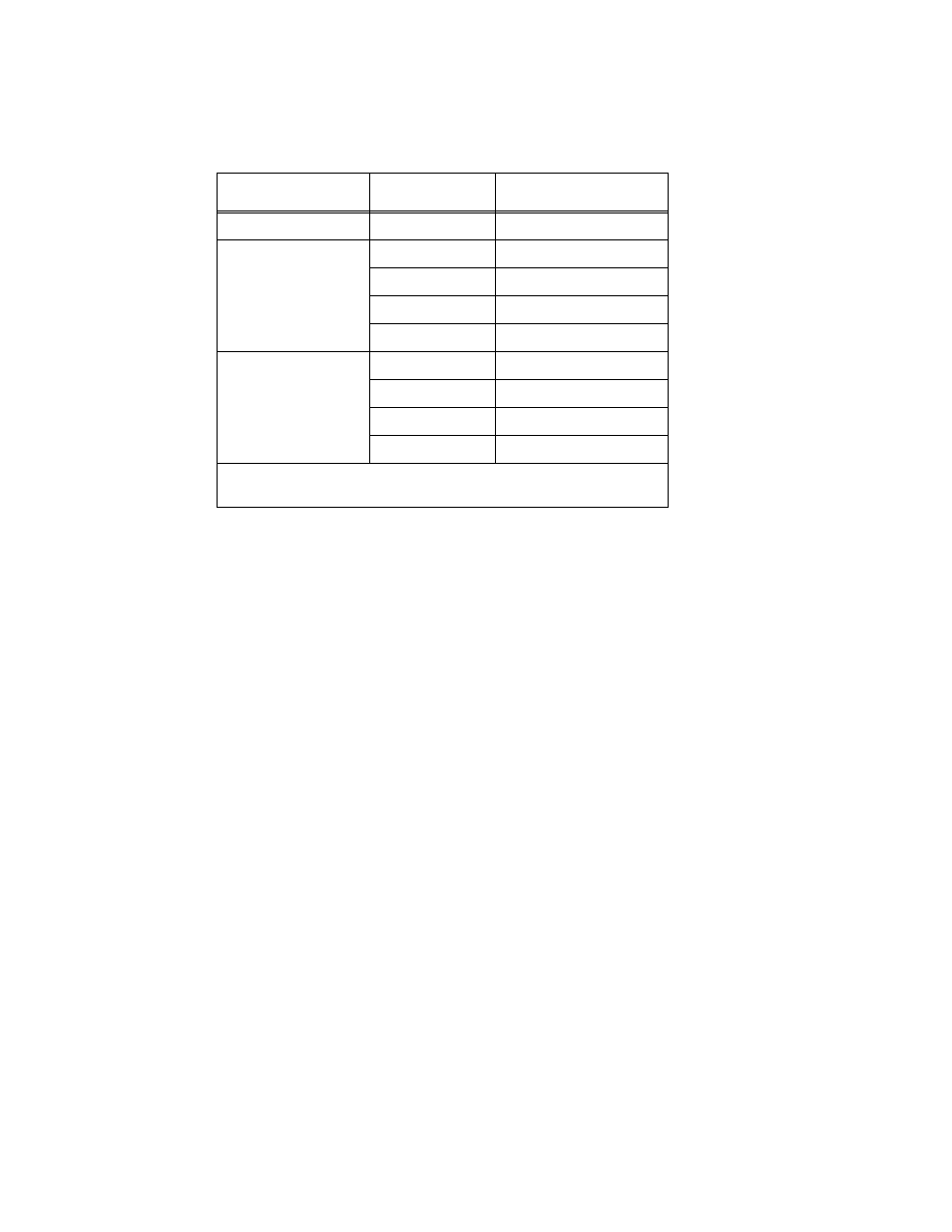
TABLE 3-4. ANALOG PROGRAMMING CONTROL VOLTAGE SCALE
MODE
RANGE
(SEE NOTE)
ANALOG CONTROL
Constant Current (CI)
Not Applicable
60 Amperes/Volt
Constant
Power
(CP)
100 Volts
6 KWatts/Volt
200 Volts
12 KWatts/Volt
400 Volts
24 KWatts/Volt
800 Volts
48 KWatts/Volt
Constant
Voltage
(CV)
100 Volts
10 Volts/Volt
200 Volts
20 Volts/Volt
400 Volts
40 Volts/Volt
800 Volts
80 Volts/Volt
NOTE: Default voltage measurement setting for CP and CV mode is auto-
range. Use SCPI commands to change ranges (see APPENDIX B).