3 calibration registers—conductivity, 1 cell offset and cell constant, Calibration registers—conductivity – In-Situ Aqua TROLL 400 Modbus and SDI-12 Reference Guide User Manual
Page 42: Cell offset and cell constant
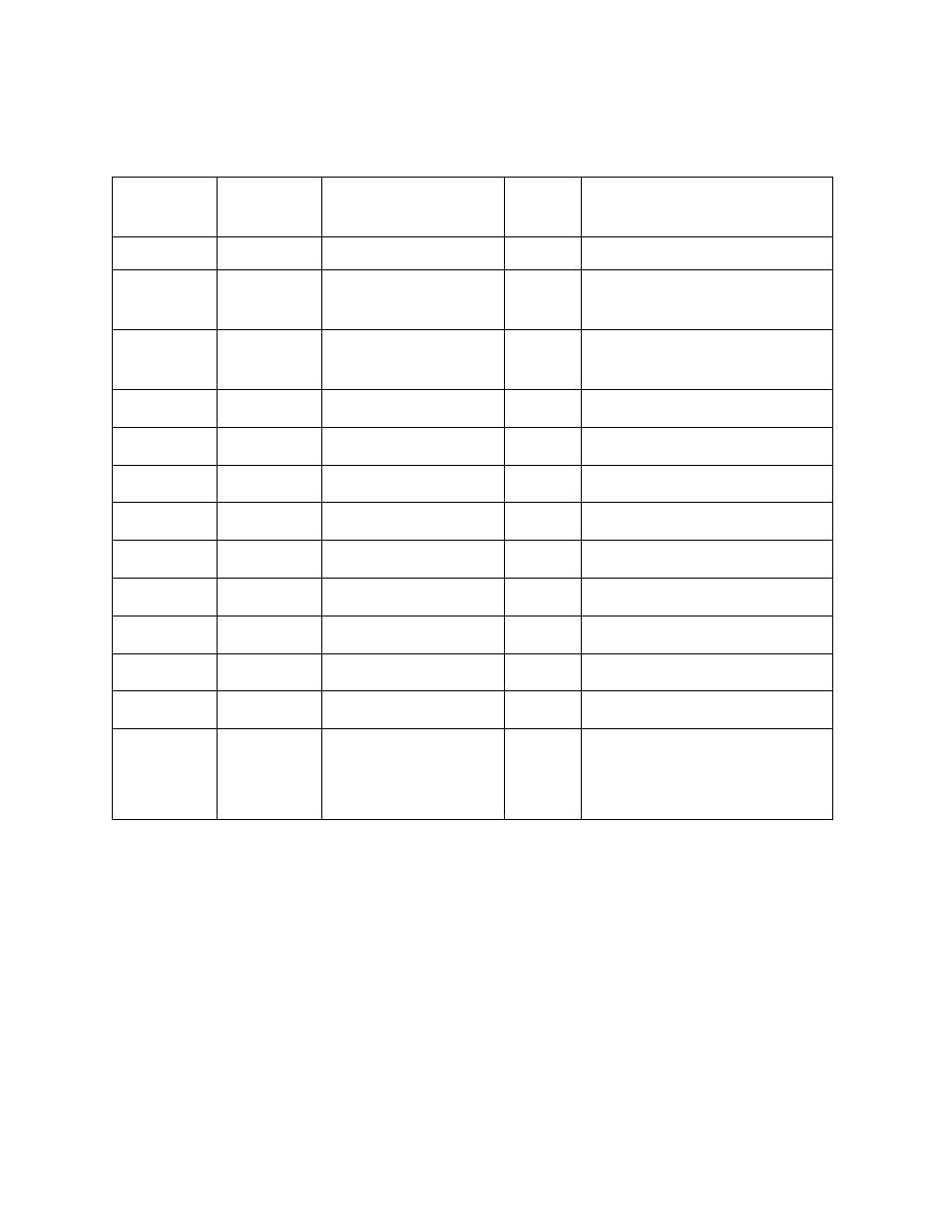
5.3 Calibration Registers—Conductivity
Values in the calibration registers determine how sensor parameters are calculated.
Register
Size
(registers)
Mode & Access Level
(R/W)
Data
Type
Description
0628
2
R1/W3
float
Cell Offset, K
0
(default = 0.0)
0630
2
R1/W3
float
Cell Constant, K
(default = 1.0)
0632
2
R1/W3
float
Reference Temperature,
T
ref
in °C (default = 25)
0634
2
R1/W3
float
Alpha Coefficient
α
(default = 0.0191)
0636
2
R1/W3
float
Beta Coefficient
β
0
(default = 1.0)
0638
2
R1/W3
float
Beta Coefficient
β
1
(default = 0.0)
0640
2
R1/W3
float
Beta Coefficient
β
2
(default = 0.0)
0642
2
R1/W3
float
Beta Coefficient
β
3
(default = 0.0)
0644
2
R1/W3
float
Beta Coefficient
β
4
(default = 0.0)
0646
2
R1/W3
float
Beta Coefficient
β
5
(default = 0.0)
0648
2
R1/W3
float
Beta Coefficient
β
6
(default = 0.0)
0650
2
R1/W3
float
Beta Coefficient
β
7
(default = 0.0)
0652
2
R1/W3
float
TDS Conversion Factor
CF
TDS
in ppm
(software limited range 0.001 to
10.000, default = 0.65, resolution
0.001)
5.3.1 Cell Offset and Cell Constant
These values are used to calibrate conductivity to user standards. These registers shall only be
able to be written when the sensor is in the calibration mode. The probe will return exception
0x92 (invalid sensor mode) if an attempt is made to write these registers when the calibration
mode is off.
Actual conductivity (AC) is calculated as follows.
AC = K
0
+ K * AC
f
Where AC
f
is the actual conductivity value computed using the factory calibrated cell constant.
For a single point calibration, K
0
is set to zero.
42