Modbus registers—probe, 1 modbus communication setup, 2 automatic salinity correction – In-Situ Aqua TROLL 400 Modbus and SDI-12 Reference Guide User Manual
Page 27: Modbus communication setup, Automatic salinity correction
3. Modbus Registers—Probe
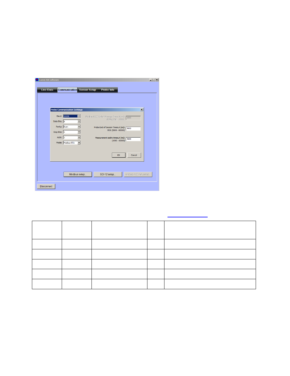
3.1 Modbus Communication Setup
See Connect the Communication Device on page 25. Click the Modbus setup button and assign
instrument settings according to the requirements of the controller.
The following Modbus registers are specific to the instrument. More information about Modbus,
including protocol specifications can be downloaded from
Register
Size
(registers)
Mode & Access Level
(R/W)
Data
Type
Description
7000
1
R1
ushort Probe Register Map Template Version (1)
7001
1
R1/W3
ushort Automatic Salinity Correction
7002
1
R1/W3
ushort Automatic Barometric Pressure Correction
7003
1
R1/W3
ushort Automatic Density Correction
7004
1
R1
ushort External Power Voltage (millivolts)
3.2 Automatic Salinity Correction
Set this register to 0 to disable automatic salinity correction. Set to 1 to enable automatic salinity
correction. The default is disabled. If disabled, the RDO sensor shall apply its live salinity
register value to correct its oxygen concentration for salinity. If enabled, the RDO sensor shall
use the salinity value from the conductivity sensor to correct its oxygen concentration for
salinity.
27