Triton FT5000 PC-BASED ATM Installation Manual User Manual
Page 47
47
NMD-100 D
ISPENSING
M
ECHANISM
R
EMOVAL
/I
NSTALLATION
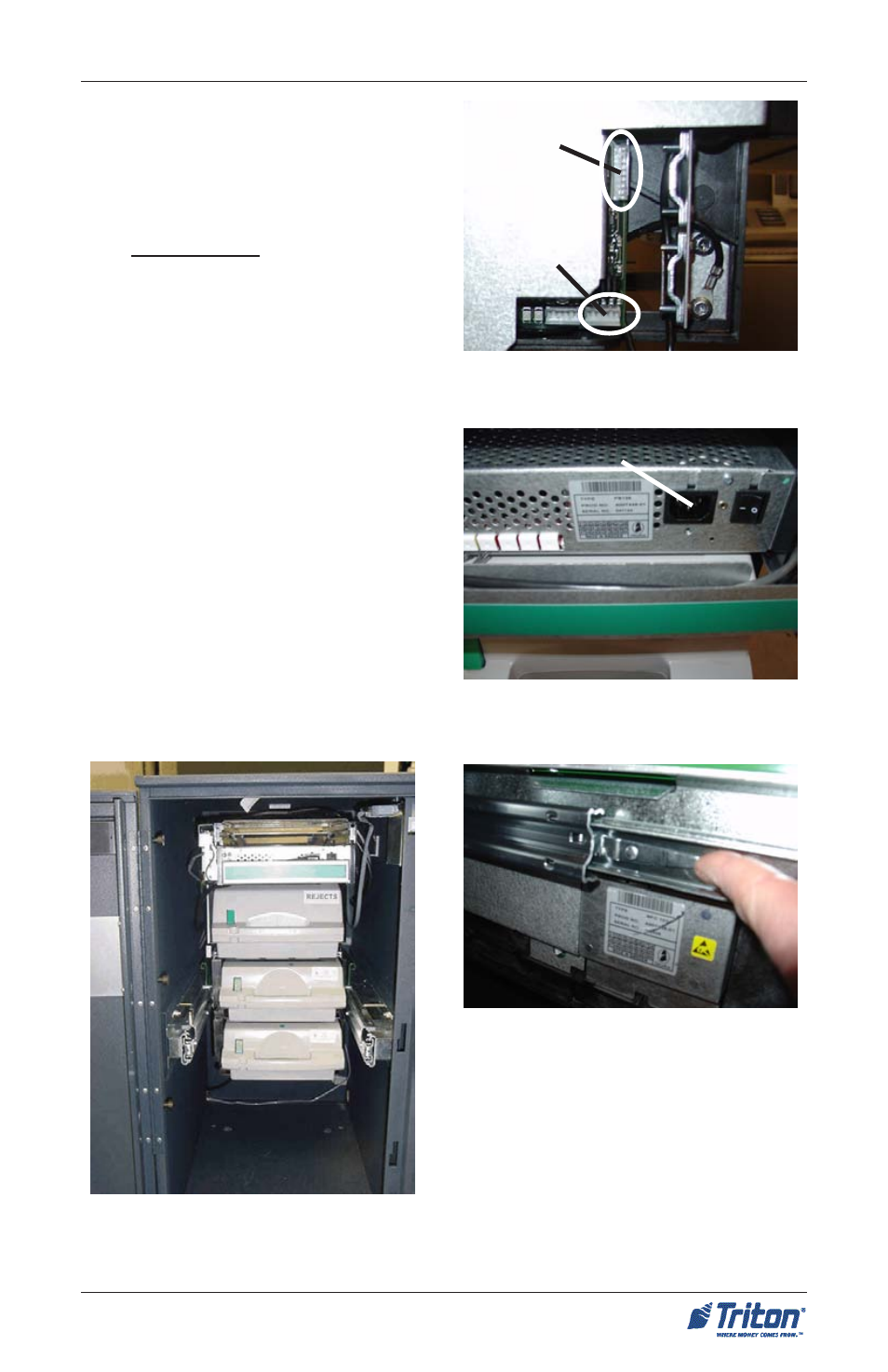
Figure 7. Slide dispenser into cabinet.
4. Refer to Figure 4. Connect the se-
rial communication data cable and
the shutter cable to the connectors
on the left side of the dispenser .
For the serial data cable, use the
forward -most connector as shown.
The plug is keyed to ensure proper
installation.
5. Connect the AC power cable to the
dispenser power supply (Figure
5).
6. Disengage the slide rails by lifting
up/down on the locking lever lo-
cated in Figure 6 (both sides). Slide
the dispenser into the cabinet until
the slide rail locking pin is engaged.
(Figure 7)
7. Turn the dispenser power switch
located just to the right of the power
connector to ON (I).
Shutter cable
connector
Serial cable
connector
Figure 4. Shutter and data cable
connectors.
Figure 5. AC power cable connection.
Figure 6. Disengage slide rails.
x
AC power cable connector
- X-SCALE/X2 Configuration Manual (419 pages)
- ARGO Installation Manual (35 pages)
- ARGO User Manual (97 pages)
- ARGO G60 Installation Manual (31 pages)
- ARGO Quick Reference Guide (10 pages)
- RL331X TRAVERSE User Manual (74 pages)
- FT5000 X2 User Manual (105 pages)
- FT5000 X2 Quick Reference Guide (10 pages)
- 81XX/91XX (including X2)/97XX/RL16XX (5 pages)
- RL1600 Installation Manual (41 pages)
- RL1600 Quick Reference Guide (7 pages)
- RL1600 User Manual (72 pages)
- RL2000 POWER CORD Installation Manual (1 page)
- RL2000 User Manual (124 pages)
- RL2000 Installation Manual (45 pages)
- RL2000 Quick Reference Guide (10 pages)
- RL5000 X2 Series User Manual (122 pages)
- RL5000 X2 Series Installation Manual (55 pages)
- RL5000 X2 Series Quick Reference Guide (12 pages)
- 8100/9100/97XX/RL5000 (X-SCALE/XP) (10 pages)
- 8100 Quick Reference Guide (6 pages)
- 8100 User/Installation Manual (150 pages)
- 9100 Installation Manual (50 pages)
- 9100 Quick Reference Guide (8 pages)
- 9100 User Manual (172 pages)
- 9100 Electronic Lock Installation Manual (8 pages)
- 96XX CASH DISPENSER CABINET Installation Manual (6 pages)
- 9650 Operation Manual (264 pages)
- 9600 Series Quick Reference Guide (2 pages)
- 9640 Operation Manual (265 pages)
- 9600 Operation Manual (209 pages)
- 9610 Series Quick Reference Guide (2 pages)
- 9610 Operation Manual (210 pages)
- 97XX Series Operation Manual (265 pages)
- 9710 Series Quick Reference Guide (2 pages)
- 9700 Series Quick Reference Guide (2 pages)
- 9705 Series Quick Reference Guide (2 pages)
- 9200 Installation Manual (26 pages)
- 9200 Operation Manual (179 pages)
- MAKO 2000 Operation Manual (217 pages)
- MAKO PEDESTAL Installation Manual (8 pages)
- MAKO EXTENDED CABINET Installation Manual (7 pages)
- RT2000 X2 User Manual (109 pages)
- RT2000 X2 Installation Manual (36 pages)
- RT2000 X2 Quick Reference Guide (8 pages)